 |
|||
|
Page Title:
Figure 10-28.--How a differential works. |
|
||
| ||||||||||
|
|
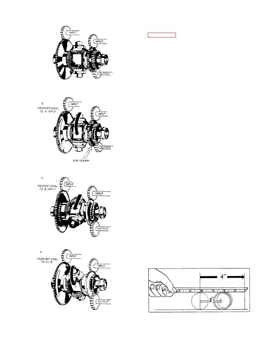 as many revolutions as the sum of the revolutions of
the end gears, because the spider gears are free to roll
between the end gears. To understand this better, look
at figure 10-29. Here a cylindrical drinking glass is
rolled along a table top by pushing a ruler across its
upper side. The glass will roll only half as far as the
ruler travels. The spider gears in the differential roll
against the end gears in exactly the same way. Of
course, the answer can be corrected by using a 2:1 gear
ratio between the gear on the spider shaft and the gear
for the output shaft. Very often, for design purposes,
this gear ratio will be found to be different.
When the two sides of the differential move in
opposite directions, the output of the spider shaft is
proportional to the difference of the revolutions of the
two inputs. This is because the spider gears are free to
turn and are driven in opposite directions by the two
inputs. If the two inputs are equal and opposite, the
spider gears will turn, but there will be no movement
of the spider shaft. If the two inputs turn in opposite
directions for an unequal number of revolutions, the
spider gears roll on the end gear that makes the lesser
number of revolutions, rotating the spider in the
direction of the input making the greater number of
revolutions. The motion of the spider shaft will be
equal to half the difference between the revolutions of
the two inputs. A change in the gear ratio to the output
shaft can then give us any proportional answer we
wish.
We have thus far been describing a hookup
wherein the two sides are inputs and the spider shaft
the output, as long as it is recognized that the spider
follows the end gears for half the sum, or difference,
of their revolutions. However, it is not necessary to
always use this type of hookup. The spider shaft may
be used as one input and either of the sides used as the
other. The other side will then become the output. This
fact permits three different hookups for any given
revolutions.
10-15
|
|
Privacy Statement - Press Release - Copyright Information. - Contact Us |
