 |
|||
|
Page Title:
Figure 10-26.--Exploded view of a differential gear system. |
|
||
| ||||||||||
|
|
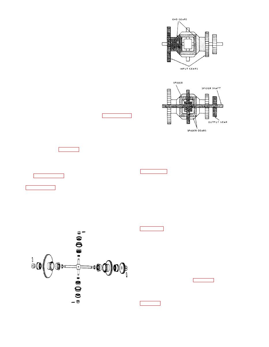 two bevel gears above and below are called spider
gears. The long shaft running through the end gears
and the three spur gears is called the spider shaft. The
short shaft running through the spider gears, together
with the spider gears themselves, is called the spider.
Each of the spider gears and the end gears are
bearing mounted on their shafts and are free to rotate.
The spider shaft is rigidly connected with the spider
cross shaft at the center block where they intersect.
The ends of the spider shaft are secured in flanges or
hangers, but they are bearing mounted and the shaft is
free to rotate on its axis. It follows then that to rotate
the spider shaft, the spider, consisting of the spider
cross shaft and the spider gears, must tumble, or spin,
on the axis of the spider shaft, inasmuch as the two
shafts are rigidly connected.
The three spur gears shown in figure 10-25
connect the two end gears and the spider shaft to other
mechanisms. They may be of any convenient size.
Each of the two input spur gears is attached to an end
gear. An input gear and an end gear together are called
differential.
a side of a differential. The third gear is the output gear
(as designated in fig. 10-25). This is the only gear that
is pinned to the spider shaft. All of the other gears,
output. Later, it will be shown that any of these three
both bevel and spur, in the differential are bearing
gears can be either an input or an output. Now, look at
mounted.
positioned by the input shafts, which represent the
differential showing each of its individual parts, and
quantities to be added or subtracted. The spider gears
do the actual adding and subtracting. They follow the
relationship of the principle parts.
rotation of the two end gears, turning the spider shaft
a number of revolutions proportional to the sum, or
For the present, we will assume that the two sides
difference, of the revolutions of the end gears.
are the inputs, and the gear on the spider shaft is the
Suppose the left side of the differential is rotated
while the other remains stationary (as in block 2 of
spider gears, making them roll on the stationary
right end gear. This motion will turn the spider in
the same direction as the input and, through the
spider shaft and output gear, the output shaft. The
output shaft will turn a number of revolutions
proportional to the input.
If the right side is now rotated and the left side held
stationary (as in block 3 of fig. 10-28), the same thing
will happen. If both input sides of the differential are
turned in the same direction at the same time, the
spider will be turned by both at once (as in block 4 of
of the two inputs. Actually, the spider makes only half
10-14
|
|
Privacy Statement - Press Release - Copyright Information. - Contact Us |
