 |
|||
|
Page Title:
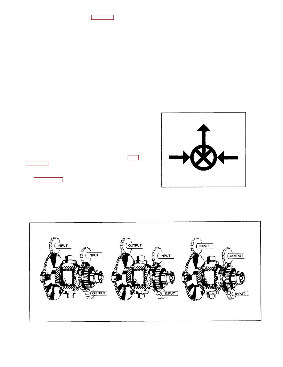
Figure 10-31.--Schematic drawing symbol for a differential. |
|
||
| ||||||||||
|
|
 designed to drive heavy loads. The outputs from such
differential (as is illustrated in fig. 10-30). Whichever
mechanisms often merely control the action of
proves the most convenient mechanically may be
used.
servomotors. The motors do the actual driving of the
loads to be handled. The device that makes it possible
for the comparatively weak output from a computing
BASIC COMPUTER
mechanism to control the action of a servomotor
MECHANISMS
is called a follow-up control. In this device, the
differential is used to measure the difference, or error,
So far, we have discussed the various gears and
in position between the input and the output. The input
what they can accomplish, and the gear differential,
is geared to one side of the differential. The servo
which is a simple analog computer. Next, we will
output is used to do two things: (1) to position
discuss basic computer mechanisms. As in all
whatever mechanism is being handled, and (2) to drive
complex machines, focus on the simple mechanisms
that comprise the complex machine. An understanding
of the simple mechanisms will enable you to
understand how they enable the complex machine to
perform its function.
The differentials used in analog computers are
gear differentials similar to those we discussed
previously, unlike the automotive differential, which
receives two inputs and combines them to provide a
single output. Most differentials used in computers
are quite small, between 2 inches x 2 1/2 inches in
size, and are designed for relatively light loads. Fig-
differential in schematic drawings.
of the gear differential in a computer. In this case, the
differential is being used as an integral part of a
follow-up control. Computing mechanisms are not
|
|
Privacy Statement - Press Release - Copyright Information. - Contact Us |
