 |
|||
|
Page Title:
Figure 10-21.--Gears can change the direction of applied motion |
|
||
| ||||||||||
|
|
 uses and advantages. But, it is better to understand
their operating theory before learning of their uses and
advantages.
single-threaded worm gear. For each revolution of the
worm gear, the worm wheel turns one tooth. Thus, if
the worm wheel has 25 teeth, the gear ratio is 25:1.
double-threaded worm. For each revolution of the
worm gear in this case, the worm wheel turns two
teeth. Thus, if the worm wheel has 25 teeth, the gear
ratio is 25:2.
Likewise, a triple-threaded worm gear would turn
the worm wheel three teeth per revolution of the worm
gear.
A worm gear-worm wheel is really a combina-
tion of a screw and a spur gear. Tremendous
motion.
mechanical advantages (M.A.) can be obtained with
this arrangement. Worm drives can also be designed
so that only the worm gear is the driver--the spur gear
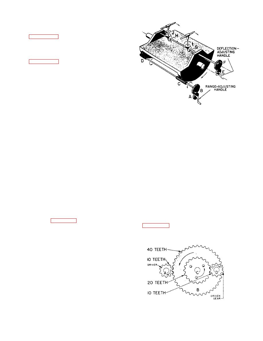
the telescopes to the right. Thus, with a simple system
cannot drive the worm gear. On a hoist, for example,
of gears, it is possible to keep the two telescopes
you can raise or lower the load by pulling on the chain
pointed at a moving target. In this and many other
that turns the worm gear. But, if you let go of the chain,
practical applications, gears serve one purpose-they
the load cannot drive the spur gear and will let the load
change the direction of motion.
drop to the deck. This is a nonreversing worm drive.
CHANGING SPEED WITH GEARS
CHANGING DIRECTION WITH GEARS
As you have already seen in the eggbeater, gears
can be used to change the speed of motion. Another
No doubt you know that the crankshaft in an
example of this use of gears is found in your clock or
automobile engine can turn in only one direction. If
watch. The mainspring slowly unwinds and causes the
you want the car to go backwards, the effect of the
hour hand to make one revolution in 12 hours.
engine's rotation must be reversed. This is done by a
Through a series, or train, of gears, the minute hand
reversing gear in the transmission, not by reversing the
makes one revolution each hour, while the second
direction in which the crankshaft turns.
hand goes around once per minute.
A study of figure 10-21 will show you how gears
are used to change the direction of motion. This is a
changes are made possible. Wheel A has 10 teeth,
schematic diagram of the sight mounts on a Navy gun.
If you trunk the range-adjusting handle, A, in a
clockwise direction, the gear, B, directly above it, is
made to rotate in a counterclockwise direction. This
motion causes the two pinions, C and D, on the shaft
to turn in the same direction as gear B against the teeth
cut in the bottom of the table. The table is tipped in the
direction indicated by the arrow.
As you turn the deflection-adjusting handle, E, in
a clockwise direction, gear F, directly above it, turns
in the opposite direction. Since the two bevel gears, G
and H, are fixed on the shaft with F, they also turn.
These bevel gears, meshing with the horizontal bevel
gears, I and J, cause I and J to swing the front ends of
|
|
Privacy Statement - Press Release - Copyright Information. - Contact Us |
