 |
|||
|
|
|||
| ||||||||||
|
|
 material. The rack and pinion in figure 10-17, view C,
Bevel Gears
are both spur gears. The rack may be considered as a
So far, most of the gears you have learned about
piece cut from a gear with an extremely large radius.
transmit motion between parallel shafts. But when
The rack-and-pinion arrangement is useful in
shafts are not parallel (at an angle), another type of
changing rotary motion into linear motion.
gear is used--the bevel gear. This type of gear can
connect shafts lying at any given angle because they
can be beveled to suit the angle.
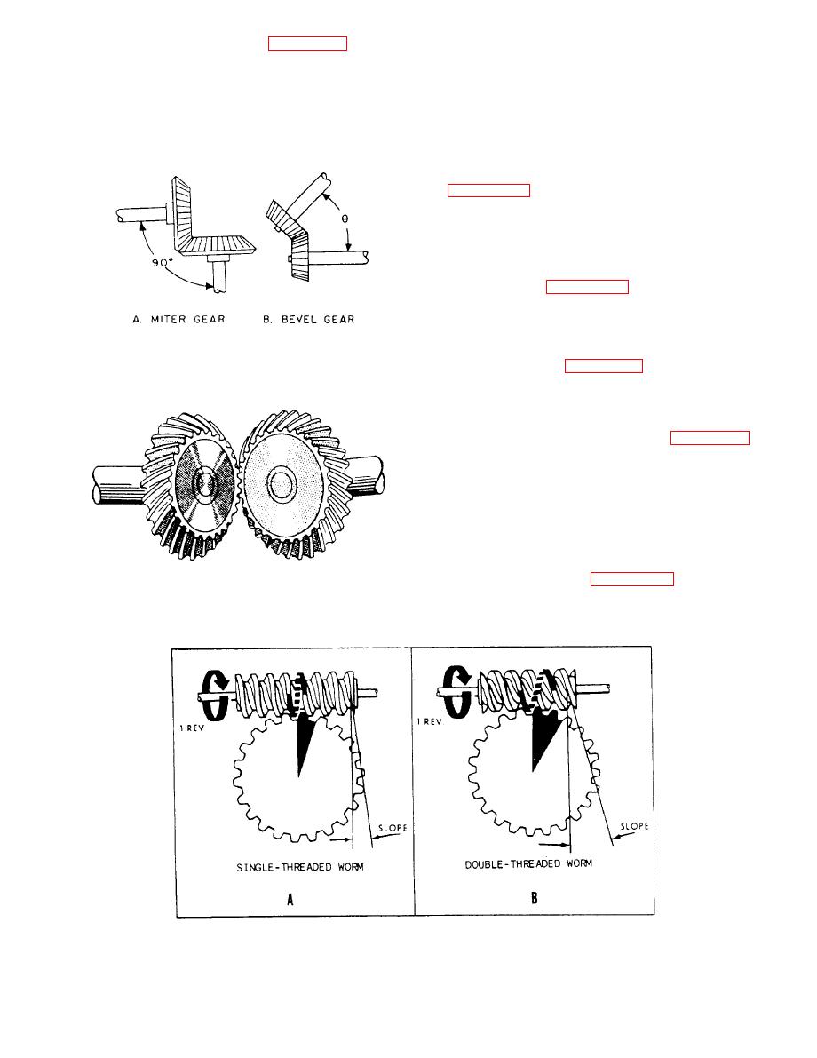
bevel gear-the miter gear. A pair of miter gears is
used to connect shafts having a 90-degree angle,
which means the gear faces are beveled at a 45-degree
angle.
You can see in figure 10-18, view B, how bevel
gears are designed to join shafts at any angle. Gears
cut at any angle other than 45 are called just plain
bevel gears.
The gears shown in figure 10-18 are called straight
bevel gears because the whole width of each tooth
comes in contact with the mating tooth at the same
time. However, some spiral level gears have teeth cut
so as to have advanced and trailing ends. Figure 10-19
is an illustration of spiral bevel gears. They have the
same advantages as other spiral (helical) gears--less
lost motion and smoother, quieter operation.
Worm Gears
Worm gears and worm gear-worm wheel
combinations, like those in figure 10-20, have many
|
|
Privacy Statement - Press Release - Copyright Information. - Contact Us |