 |
|||
|
Page Title:
Figure 10-16.--Herringbone gears. |
|
||
| ||||||||||
|
|
 contact. This kind of meshing action keeps the gears
in constant contact with one mother; therefore, less
lost motion and smoother, quieter action is possible.
One disadvantage of this helical spur gear is the
tendency of each gear to thrust or push axially on its
shaft. A special thrust bearing must be put at the end
of the shaft to counteract this thrust.
Thrust bearings are not needed if herringbone
gears like those shown in figure 10-16 are used. Since
the teeth on each half of the gear are cut in opposite
directions, each half of the gear develops a thrust that
counterbalances that of the other half. You'll find
herringbone gears used mostly on heavy machinery.
in common use.
In helical gears, the teeth are cut slantwise across
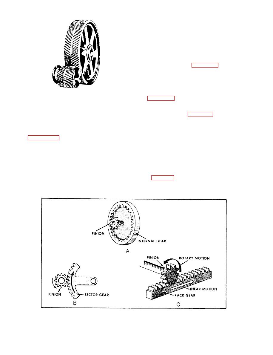
The internal gear in figure 10-17, view A, has teeth
the face of the gear. One end of the tooth, therefore,
on the inside of a ring, pointing inward toward the axis
lies ahead of the other. In other words, each tooth has
of rotation. An internal gear is always meshed with an
a leading end and a trailing end. A look at these gears
external gear, or pinion, whose center is offset from
in figure 10-15 will show you how they are
the center of the internal gear. Either the internal or
constructed.
pinion gear can be the driver gear, and the gear ratio
is calculated the same as for other gears-by counting
In the straight spur gears, the whole width of the
teeth.
teeth comes in contact at the same time. But with
helical (spiral) gears, contact between two teeth starts
Often only a portion of a gear is needed where the
first at the leading ends and moves progressively
motion of the pinion is limited. In this case, the sector
across the gear faces until the trailing ends are in
gear (fig. 10-17, view B) is used to save space and
Figure 10-17.--Gear arrangements.
10-9
|
|
Privacy Statement - Press Release - Copyright Information. - Contact Us |
