 |
|||
|
Page Title:
Figure 10-13.--A simple gear arrangement. |
|
||
| ||||||||||
|
|
 A simple gear system that illustrates all of these
functions is the eggbeater (fig. 10-13). There are 32
teeth on gear A, which mesh with 8 teeth on gear B.
Notice the direction of rotation. Also notice that as
gear B turns in one direction, its teeth mesh with gear
C and cause C to revolve in the opposite direction. The
rotation of the crank handle has been transmitted by
gears A, B, and C to cause the beater blades to rotate.
Gears also can change the speed of the motion, as
was stated previously. Since gear A has 32 teeth and
gear B has only 8, one complete revolution of gear A
causes four complete revolutions of gear B. Therefore,
the ratio between A and B is 1:4. Since gear C also has
8 teeth, the ratio of B to C is 1:1. Therefore, the beater
blades revolve four times as fast as the crank handle.
Gears also can change the force of the applied
motion. Generally, any time a gear is used to increase
the speed of motion, the force at the output of the gear
Spur Gears
is reduced. Conversely, when the speed is reduced by
gears, the force at the output is increased.
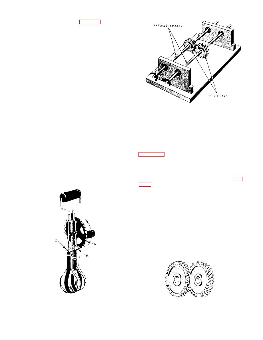
When two shafts are not lying in the same straight
line but are parallel, motion can be transmitted from
TYPES OF GEARS
one to the other by spur gears. This setup is shown in
There are several types of gears used in
Spur gears are wheels with mating teeth cut in
mechanical assemblies. In the following paragraphs,
their surfaces so that one can turn the other without
we will discuss the spur, bevel, and worm gears.
slippage. When the mating teeth are cut so that they
are parallel to the axis of rotation (as shown in fig.
When two gears of unequal size are meshed
together, the smaller of the two is usually called a
pinion. By unequal size, we mean an unequal number
of teeth causing one gear to be of a larger diameter
than the other. The teeth, themselves, must be of the
same size in order to mesh properly.
The most commonly used type of spur gear is the
straight spur gear, but quite often you will run across
another type of spur gear called the helical spur gear.
|
|
Privacy Statement - Press Release - Copyright Information. - Contact Us |
