 |
|||
|
Page Title:
Figure 10-1.--Ship's control console. |
|
||
| ||||||||||
|
|
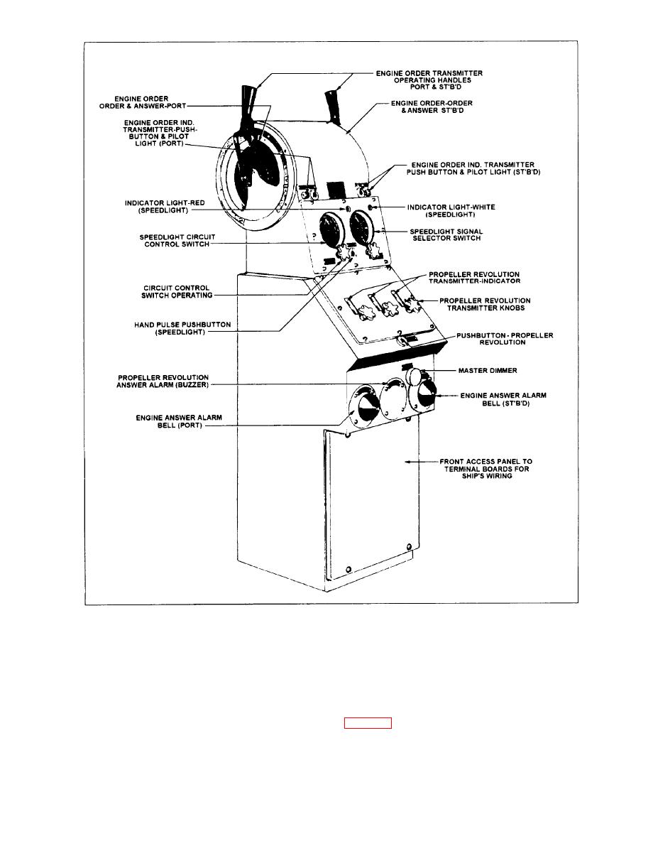 indicator transmitter when a change in propeller
gauge board. The control unit (propeller order
indicator transmitter) for circuit M is mounted in the
revolutions is ordered by the OOD.
ship's control console. It is a self-synchronous control
A second propeller order indicator-transmitter
unit, containing three synchro transmitters and three
synchro receivers, each of which is coupled to an
engine room No. 1. When a change in propeller
indicating dial. The transmitters are further coupled to
revolutions is transmitted from the ship's control
control knobs. The lee helmsman operates the
10-2
|
|
Privacy Statement - Press Release - Copyright Information. - Contact Us |
