 |
|||
|
Page Title:
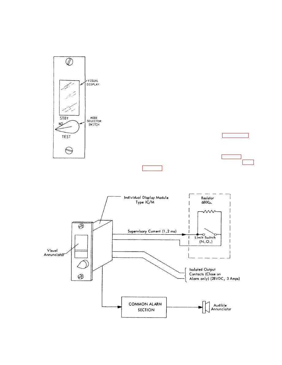
Figure 9-19.--Individual alarm display module. |
|
||
| ||||||||||
|
|
 BATTERY CHARGER.-- The battery charger
conditions. However, it does not supply emergency
provides a floating charge to maintain the battery
power to operate the switchboard. The battery also
during normal switchboard operation. When the
supplies power to operate the alarm silence indicator
battery is charging, the battery voltage should be
when the visual-audible switch is in the VISUAL
position.
between 12 and 13.8 volts.
COMMON BOARD.-- The common board
contains the relays and circuitry to actuate all alarms.
It also contains the circuitry for ground detection,
dimming, and flashing lamp power.
for each lo-line display alarm module. Each power
supply consists of a transformer and a bridge rectifier.
The output voltage of each power supply is approx-
imately 6.3 volts.
Line Display Section
The lower section of the switchboard is called the
line display section. This section contains all the
individual line display alarm modules. Figure 9-19 is
an illustration of an individual alarm display module.
Recognition of the state of the remote sensor
is accomplished by the alarm module (fig. 9-19). One
module is associated with each line circuit. Fig-
sensor circuit. A sensor circuit will be in one of three
|
|
Privacy Statement - Press Release - Copyright Information. - Contact Us |
