 |
|||
|
Page Title:
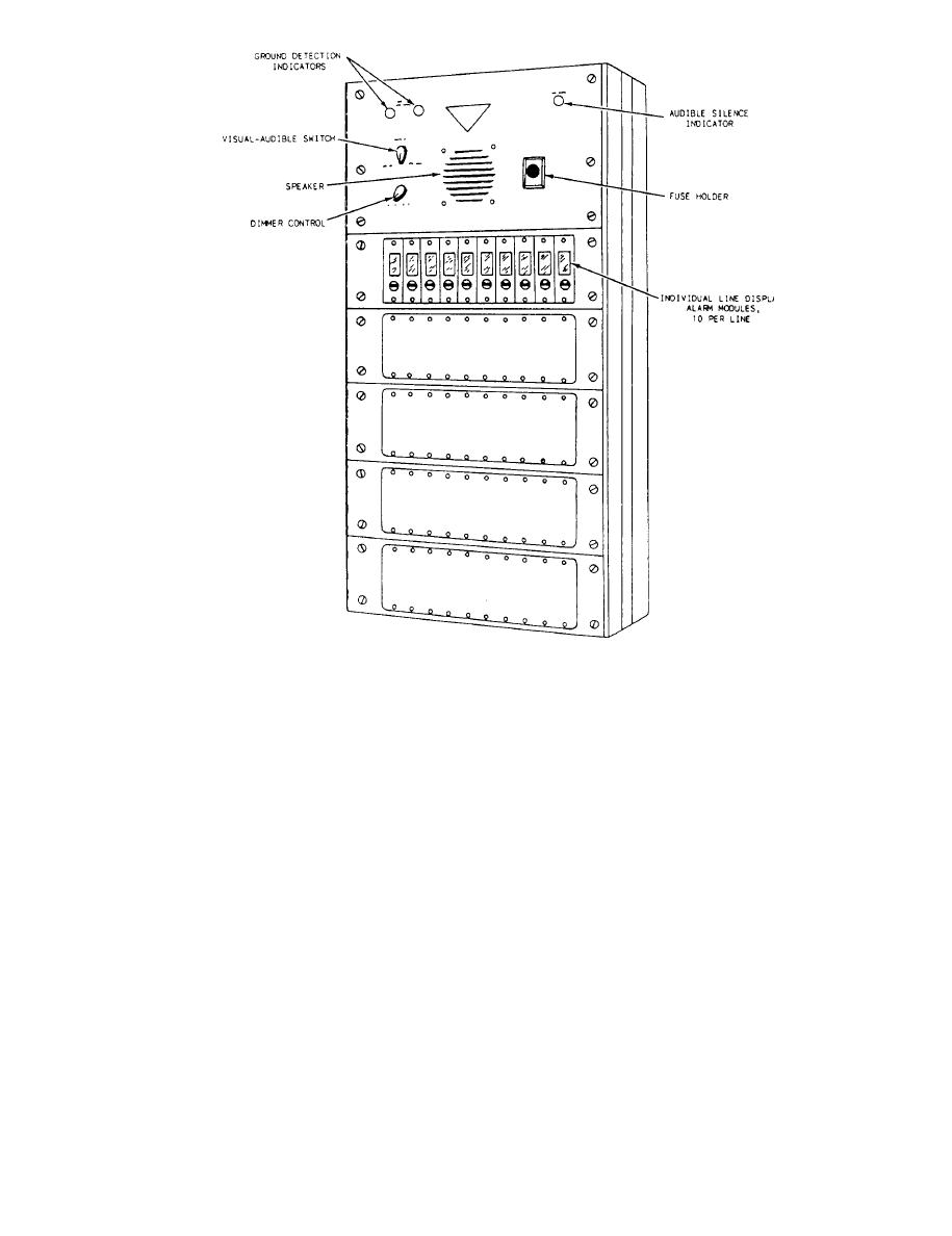
Figure 9-18.--IC/SM-50 alarm switchboard with 10 active modules in place. |
|
||
| ||||||||||
|
|
 AUDIBLE VOLUME CONTROL.-- T h e
indicate an existing alarm condition. This switch is
audible volume control is used to adjust the volume of
normally left in the AUDIBLE position.
the speaker.
ALARM SILENCE INDICATOR.-- The alarm
silence indicator illuminates when the visual-audible
TONE GENERATOR.-- The tone generator is a
switch is in the VISUAL position.
type IC/E3D2 electronic signal unit. The tone generator
receives inputs from the alarm relays located in the
DIMMER CONTROL.-- The dimmer control
common board and, in turn, generates the appropriate
dims the alarm module display lamps in all conditions
audible signal over the speaker. A wailing tone is gen-
except flashing.
erated for an alarm condition. A steady tone is generated
SPEAKER.-- The speaker sounds an audible
for a supervisory failure (trouble condition), and a pul-
alarm when the visual-audible switch is set in the
sating tone is generated when there is a loss of power.
AUDIBLE position.
BATTERY.-- The battery supplies power to the
FUSE HOLDER.-- The fuse holder contains the
tone generator to generate the pulsating tone when
two main power fuses for the switchboard. If either fuse
primary power fails. The battery must be hooked
blows, the fuse holder will illuminate to indicate that
up for the switchboard to operate under normal
there is a blown fuse.
9-18
|
|
Privacy Statement - Press Release - Copyright Information. - Contact Us |