 |
|||
|
Page Title:
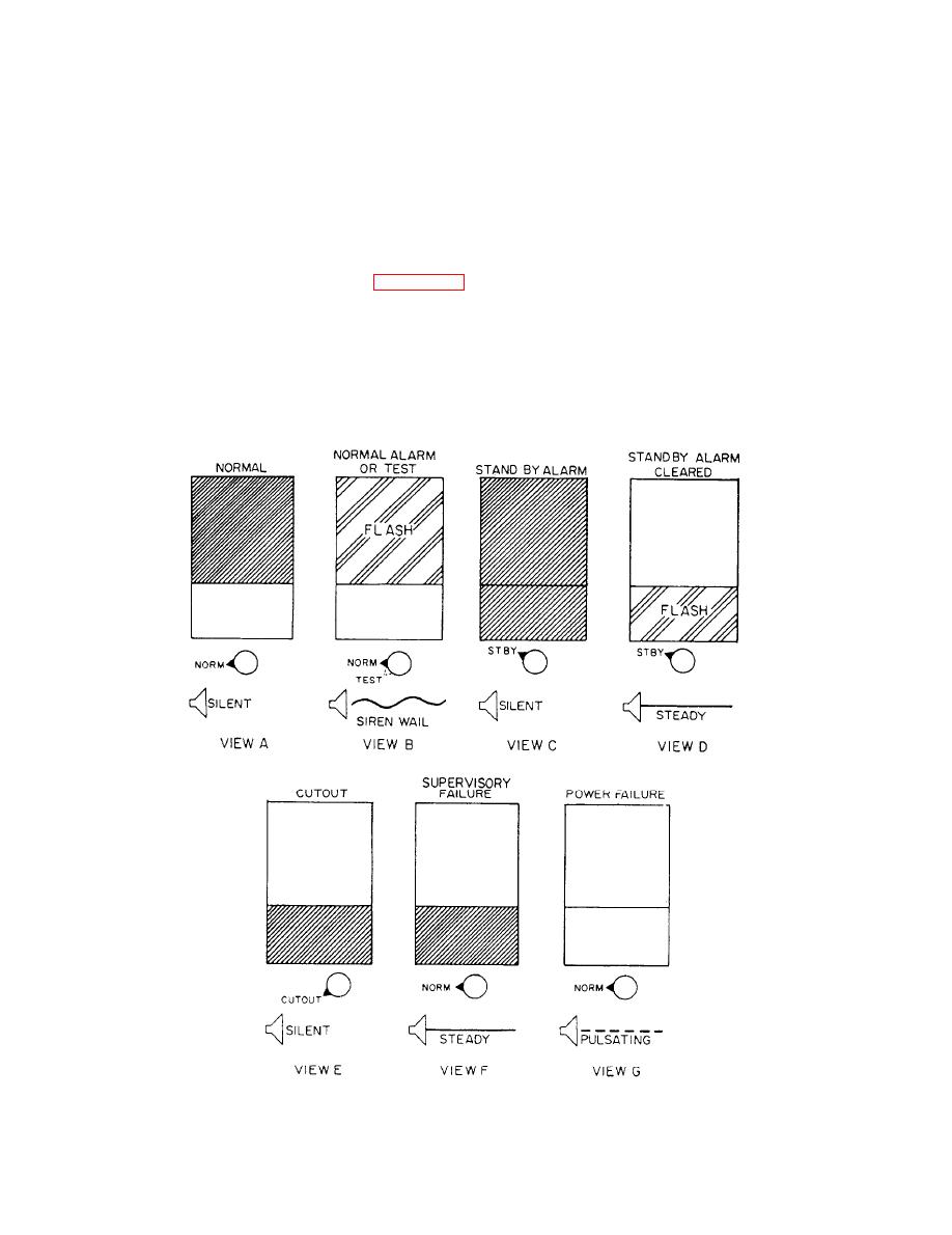
Figure 9-21.--Visual displays and audible outputs. |
|
||
| ||||||||||
|
|
 conditions: normal, alarm condition, or supervisory
place the module in either the NORM (NORMAL),
failure. The upper rectangular portion on the module
STBY (STANDBY), CUTOUT, or TEST mode.
panel gives the visual display of the circuit condition.
NORMAL MODE.-- The NORMAL mode is the
Each module contains a horizontally centered,
normal operating position of the mode switch. In this
mode, the upper display lamp is on (steady) and the
divided display that can present a steady or flashing
lower display lamp is off (dark). There will be no
red light or no light in either half of the display. All
audible signal. When the remote sensor contacts close,
light modes can be dimmed except the flashing mode.
an alarm condition occurs. During an alarm condition,
The upper half of the display shows the circuit
the upper display lamp flashes continuously and the
designation and the location of the sensor. The
lower display lamp remains off. The alarm module
condition of a remote sensor by the alarm module is
sends a command to the common alarm section. The
indicated by visual and audible signals. Figure 9-21
tone generator in the common alarm section activates
illustrates the visual and audible displays of an alarm
the alarm speaker, and a siren wail is heard.
module.
During a trouble condition, such as an open
Each module also has a four-position mode
circuit, with the mode switch in NORM, the alarm
selector switch. The mode selector switch is used to
module will signal a supervisory failure. In this
9-20
|
|
Privacy Statement - Press Release - Copyright Information. - Contact Us |