 |
|||
|
Page Title:
Figure 8-2.--Amplifier control panel. |
|
||
| ||||||||||
|
|
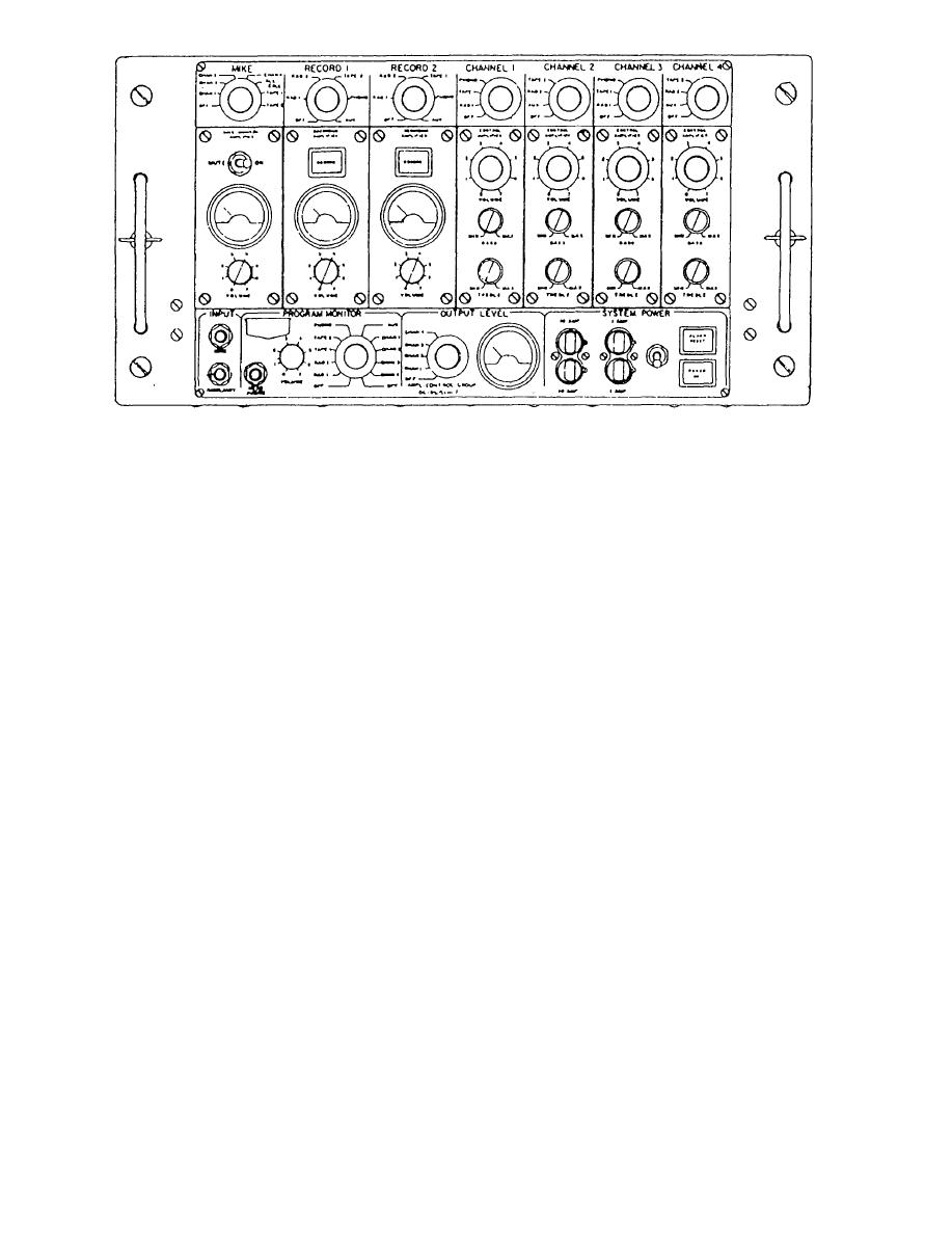 panel. This section contains the switch for energizing
this feature, you should turn off all local loudspeakers
the system, a power-on indicator lamp, an alarm reset
and keep the surrounding noise to a minimum.
indicator lamp, and four blown fuse indicators.
The mute-on switch disables the microphone
When the power-on switch is in the up position,
signal when the microphone is not in use. This switch
the system will be energized and the power-on
is also used to adjust the output volume of the
indicator lamp will be lighted.
microphone before using it. To adjust the output
volume, speak into the mike and adjust the volume
control until the signal just peaks into the red region
When an alarm is transmitted over circuit 1MC,
of the volume meter.
the alarm reset indicator lamp will light and will
remain lighted after the alarm has ceased. The entire
To interrupt a program using a microphone,
system will automatically be deactivated whenever an
switch the microphone selector to that channel.
alarm condition exists. The alarm reset indicator lamp
Switch the channel program selector switch to an
must be pressed to automatically reactivate the system
unused position and set the channel volume control to
following an alarm condition.
the minimum position. To add voice to a channel
program, switch the mike selector to that channel, The
The two 10-amp fuses are main system power
voice signal will mix equally with the other program
fuses, and the two 1-amp fuses are control power
material. To fade out the normal program, turn the
fuses.
channel volume control down.
MIKE CONTROL SECTION.-- The mike
To add voice to a tape recording, set the
control section is located on the left side of the panel.
microphone selector switch to the desired tape. Voice
This section contains a microphone input jack, a
and program can now be mixed and faded together as
selector switch to select routing of the microphone
described in channel operation.
signal, a mute-on switch, a volume control, and a
volume meter. Low- and medium-impedance
The microphone ALL CALL selector position is
microphones are used with the system. When using
a special function that interrupts all channels
8-3
|
|
Privacy Statement - Press Release - Copyright Information. - Contact Us |
