 |
|||
|
Page Title:
Figure 4-36.--Block diagram of the complete alarm system. |
|
||
| ||||||||||
|
|
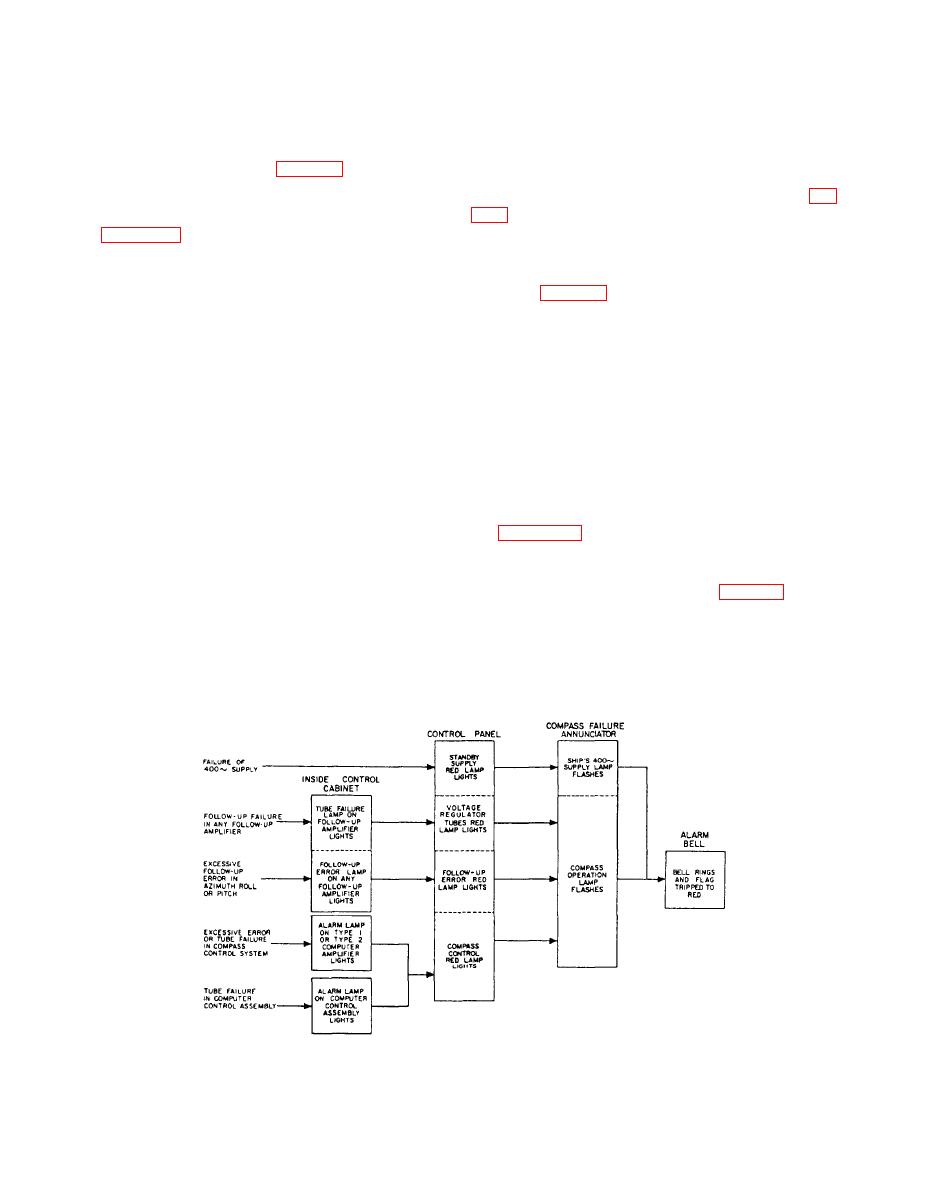 any tube in the assembly becomes defective. A failure
the system will give multiple alarm warnings when
in any loop circuit will actuate the alarm and cause a
trouble develops in that loop. In addition, as trouble may
neon indicating lamp to light on the associated computer
also develop in the alarm circuits, the circuits are so
amplifier, or amplifiers, and any tube failure in the
arranged as to give alarm warnings when they
computer control assembly will cause a similar
themselves become defective. This is accomplished in
indicating lamp to light on the computer control
each alarm circuit by using normal tube current to
assembly panel.
energize an alarm relay. (See fig. 4-34). Therefore, if
trouble develops within that circuit to reduce tube
The ship's 400-Hz supply alarm (not shown in fig.
current, the relay will de-energize and actuate the alarm.
the ship's 3-phase, 400-Hz supply, or a drop supply
voltage below 104 volts. Undervoltage detection
each loop in the system is alarmed. This figure does not
circuits and associated relays in the system control
show every alarm that will give warning, but merely the
place in the loop where the initial alarm will occur. The
assembly (fig. 4-24) actuate the alarm, disconnect the
complete alarm system may be divided into four
compass from the ship's supply line, and operate the
separate systems: the follow-up alarm system, the
standby supply as a generator. The ship's supply
indicating light (green) on the control panel goes out and
compass control alarm system, the ship's 400-Hz supply
the standby supply light (red) comes on, showing that
alarm system, and the voltage regulator alarm system.
the ship's 400-cycle supply has failed and that the
The follow-up alarm system consists of two alarm
compass is operating on the standby supply.
circuits in each follow-up amplifier. As the three
The voltage regulator failure alarm gives a visual in-
follow-up amplifiers are identical, the alarms in each are
dication of a tube failure in the differential amplifier and
identical. The alarm circuits are the preamplifier tube
for an out-of-tolerance input voltage. A voltage in excess
failure alarm and the follow-up error alarm. Two neon
of 122 volts or less than 108 volts will actuate the alarm.
indicating lamps on each amplifier are provided to give
a visual indication of the source of trouble when an
alarm is actuated.
the complete alarm system. The flashing lamps in the
compass failure annunciator are actuated by flasher
The compass control alarm system consists of nine
units in the system control assembly (fig. 4-24).
computer loops and four torque loops. These 13
computer and torque loops have associated with them
Starting Control Systems
11 type 1 and 2 type 2 computer amplifiers, with alarm
circuits. Also, each of the compass control signals pass
To aid in starting and operating the master compass,
through the computer control assembly. An alarm circuit
two auxiliary control systems are provided; the starting
is employed that will actuate the compass alarm when
system and the fast-settling system.
|
|
Privacy Statement - Press Release - Copyright Information. - Contact Us |
