 |
|||
|
Page Title:
Fignre 4-24.--System control assembly. |
|
||
| ||||||||||
|
|
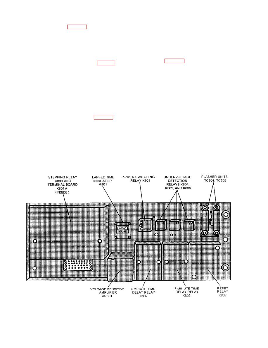 SYSTEM CONTROL ASSEMBLY.-- The
VOLTAGE REGULATOR.-- Because a supply
voltage fluctuation even as low as 2 volts can cause
system control assembly (fig. 4-24) is mounted at the
compass errors, a voltage regulator was developed for
top of the rear section of the control cabinet and includes
the Mk 19 Mod 3A system. This regulator is designed
switches, a time delay and circuits, and a stepping relay
to be installed in the bottom of the control cabinet and
for cycling the events automatically. These components
provides an output of 115 volts, 400 Hz ac regulated
are required for starting and operating the compass
within 0.75 volt for an input of 115 volts 7 volts. The
system. They operate in conjunction with the switches,
regulator unit (fig. 4-25, view B) is a single chassis
indicators, and relays on the control panel (fig. 4-22) and
containing a diode rectifier circuit, a dc reference circuit,
elsewhere in the system in performing starting and
a differential amplifier, and a corrector circuit. The
control functions.
corrector circuit includes a magnetic amplifier, a
FOLLOW-UP AMPLIFIERS.-- Mounted below
servomotor and gear train, a variable autotransformer,
and a buck-boost transformer. The buck-boost
the system control assembly are the roll, pitch, and
transformer aids or opposes the line voltage with a
azimuth follow-up amplifiers. The three follow-up
voltage supplied from the autotransformer.
amplifiers are identical and interchangeable.
An alarm indicator tube is provided to indicate a
tube failure and an out-of-tolerance input voltage. In
amplifiers is the dc power supply unit (fig. 4-25, view
addition, the unit contains a magnetic amplifier balance
A) containing the power supply component (metallic
control, a nominal voltage adjustment control, an
rectifiers, filters, and so forth), a monitoring meter, and
automanual switch, and an ac voltmeter to indicate the
an associated selector switch. The unit operates from the
regulated output voltage.
115-volt, 4(X)-HZ, 3-phase supply and furnishes all dc
voltages required for the operation of the various
ADDITIONAL COMPONENTS.-- In addition to
amplifiers and relays in the system.
the components and assemblies previously mentioned,
4-19
|
|
Privacy Statement - Press Release - Copyright Information. - Contact Us |
