 |
|||
|
Page Title:
Figure 4-33.--Block diagram of the data correction system. |
|
||
| ||||||||||
|
|
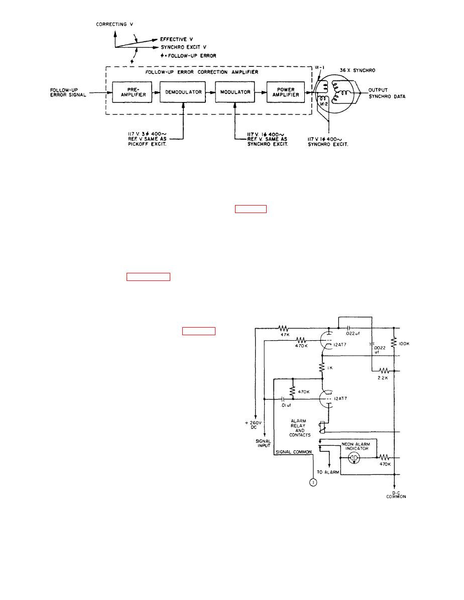 follow-up system, as mentioned previously. The
reference. The demodulator output (a dc voltage propor-
meridian gyro roll-pitch pickoff signal is fed to one
tional to the pickoff signal) is modulated using the
resolver rotor winding, and the slave gyro roll-pitch
synchro excitation voltage as a reference (as shown in
pickoff signal is fed to the other rotor winding. The
resolver functions to resolve its own ship's course and
synchro rotor winding is a voltage proportional to the
roll-pitch pickoff input signals into output signals of
follow-up error; thus the transmitted data is corrected
proper proportions to the follow-up amplifiers. The
by an amount equal to the follow-up error. The
follow-up motors position the roll-pitch phantom until
transmitted data then indicates the true attitude of the
the pickoffs are restored to their neutral position and, at
gyros rather than the phantom ring assembly.
the same time, position 2- and 36-speed roll and pitch
Alarm System
synchro data transmitters. Figure 4-32 shows a block
diagram of the roll-pitch follow-up sequence.
An alarm system is incorporated in the Mk 19 Mod
3A gyrocompass system to the extent that each loop in
Due to backlash, spring in gearing, and other effects,
follow-up motors may have errors up to 0.05. These
errors are compensated for in the Mk 19 gyrocompass
by a data correction system (shown only in fig. 4-33).
Three special type synchro transmitters are used with
three transistor data correction amplifiers in
transmitting the 36-speed heading, roll, and pitch data.
Each 36-speed synchro transmitter has an additional
rotor winding displaced 90 electrical degrees from the
normal rotor winding. When this additional, or
quadrature, rotor winding (W1) is excited by a variable
voltage, the magnetic field produced reacts with the
magnetic field of the normal rotor winding (W2), and
thus produces a resultant rotor field that is displaced
from the normal rotor winding field. The angle of this
displacement is proportional to the magnitude and phase
of the voltage applied to the additional rotor winding.
The three transistor data correction amplifiers are
sealed and mounted in the bottom of the master
compass. The input signals to the amplifier area portion
of the azimuth follow-up signal, roll follow-up signal,
and pitch follow-up signal. The signal is amplified and
alarm relay.
demodulated using the pickoff excitation voltage as a
|
|
Privacy Statement - Press Release - Copyright Information. - Contact Us |
