 |
|||
|
Page Title:
Figure 4-29.--Earth rate and constant torque compensation signals. |
|
||
| ||||||||||
|
|
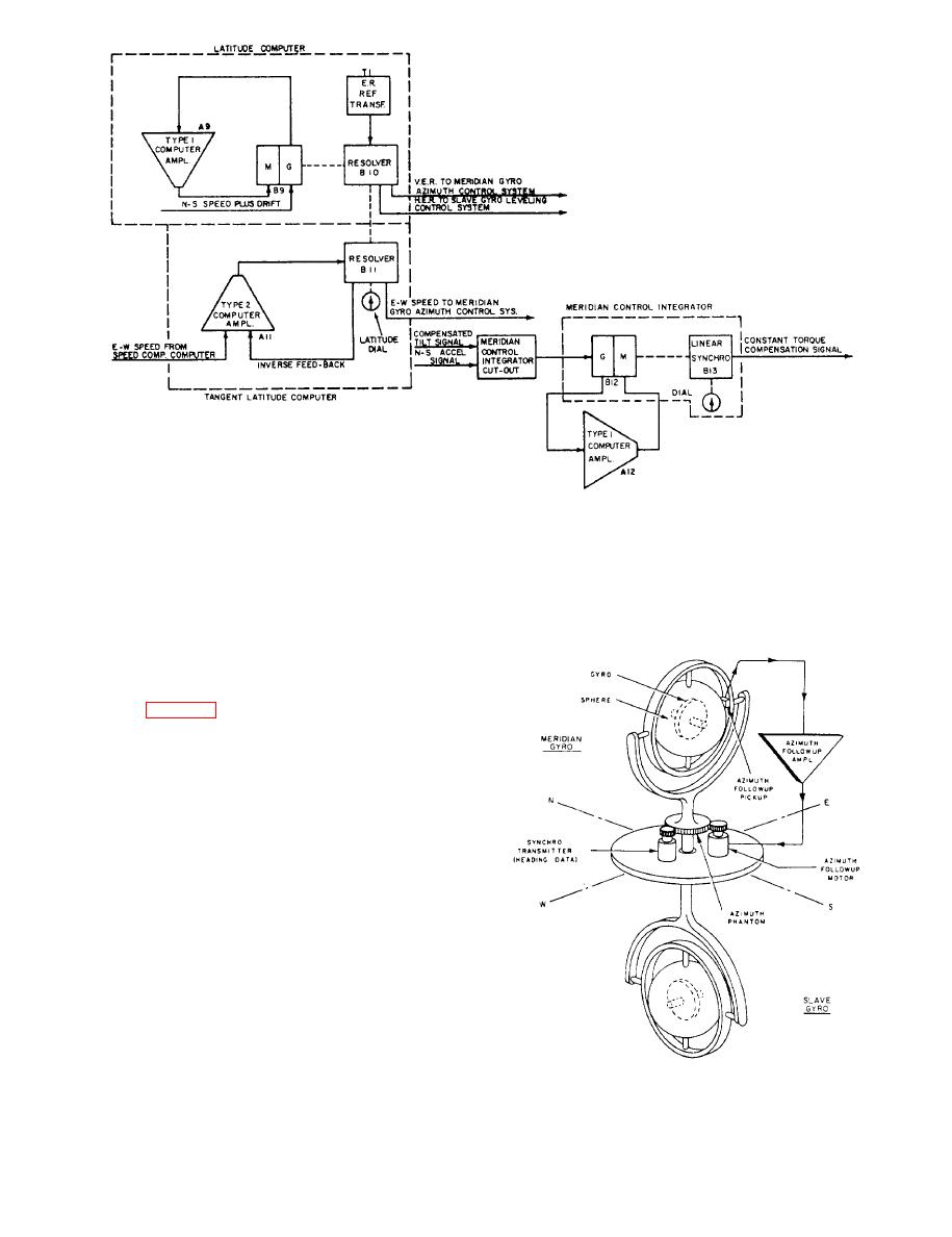 signal from the electrolytic bubble level is not zero, and
speed and the reciprocal of the cosine of the latitude.
persists for a long period of time, such as mechanical
This output signal on the rotor of the resolver is
unbalance of the compass would cause, the rotor of the
multiplied by the sine of the ship's latitude in the sine
linear synchro (B 13) will turn gradually at a constant
stator winding, being proportional to the product of
rate. The output voltage, being of opposite phase to the
east-west speed and the tangent of the ship's latitude;
the signal is the meridian gyro east-west speed
compensation signal.
system (fig. 4-29) consists of a type 1 amplifier, an
integrator cutout, and a meridian control integrator. The
meridian control integrator includes a motor-tachometer
(B12) and a linear synchro (B13). The dial provides
visual indication of integrator operation.
The meridian gyro compensated tilt signal is fed
through a relay in the integrator cutout, in series with
the damping voltage output of the generator section of
the motor-tachometer (B13) to the input of the type 1
computer amplifier.
The amplifier output drives the motor section of the
motor-tachometer (B12), which is geared down (3
million to 1) to the linear synchro. Because of this high
gear reduction, it takes a great number of motor
revolutions over a period of time to appreciable y rot ate
the rotor of the linear synchro (B 13). The linear synchro,
therefore, for all practical purposes, does not respond to
short-time signals, but responds to long-time signals or the
system.
sum of fluctuating and short-time signals. If the average
4-28
|
|
Privacy Statement - Press Release - Copyright Information. - Contact Us |
