 |
|||
|
Page Title:
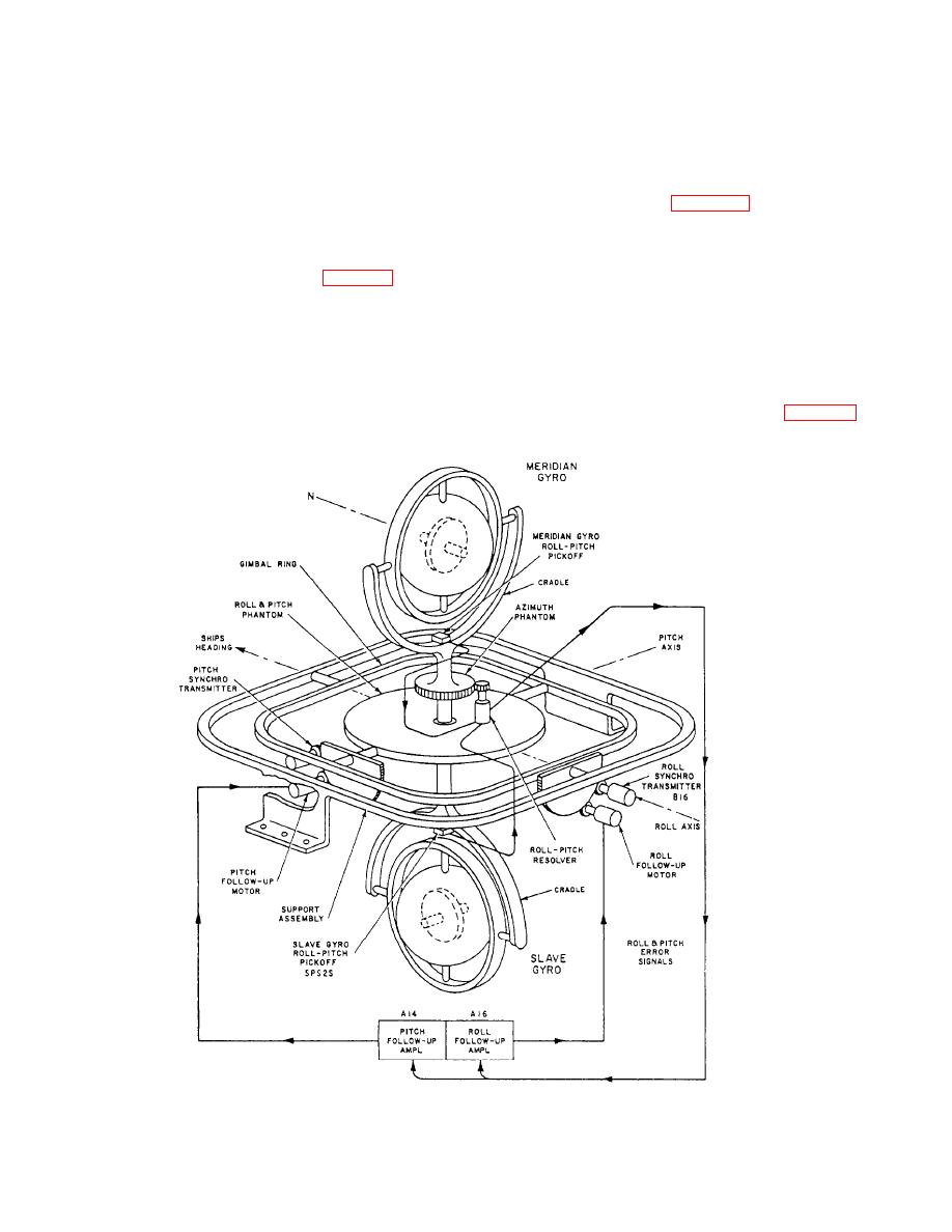
Figure 4-31.--Simplified diagram of the roll and pitch follow-up system. |
|
||
| ||||||||||
|
|
 misalignment signal to the follow-up amplifier in the
tilt signal input, will tend to reduce the input slowly until
conventional manner. The follow-up motor, driven by
the voltage output of the linear synchro exactly equals
the azimuth follow-up amplifier output, drives the
the tilt signal input caused by the unbalance.
azimuth phantom, restoring the azimuth pickoff to its
The time constant, or rate of change, of the linear
neutral position and positioning, through gearing, the 1-
synchro output voltage for a given tilt signal is made slow
and 36-speed heading data synchro transmitters. The
enough so as not to affect the normal settling character-
follow-up motor also positions the rotor of the roll-pitch
istics of the compass, and yet fast enough to compensate
resolver (not shown in fig. 4-30) to a position
for any constant torque without appreciable delay.
corresponding to ship's heading.
Azimuth Follow-up System
The azimuth follow-up amplifier consists of a
preamplifier stage, a demodulator stage with displace-
The azimuth follow-up system (fig. 4-30) detects
ment and rate signal networks, and a magnetic amplifier
any misalignment between the vertical ring and the
output stage. Associated with the amplifier are two
gyrosphere and functions to drive the azimuth phantom,
alarm circuits, which actuate the compass alarm in case
and therefore the vertical ring, back into alignment with
of excessive pickoff signal or preamplifier tube failure.
the gyrosphere.
Roll and Pitch Follow-up System
An azimuth pickoff, consisting of an E-shaped core
transformer mounted on the vertical ring and an
The roll and pitch follow-up system (fig. 4-31)
detects and eliminates any misalignment between the
armature cemented to the gyrosphere, furnishes the
|
|
Privacy Statement - Press Release - Copyright Information. - Contact Us |
