 |
|||
|
Page Title:
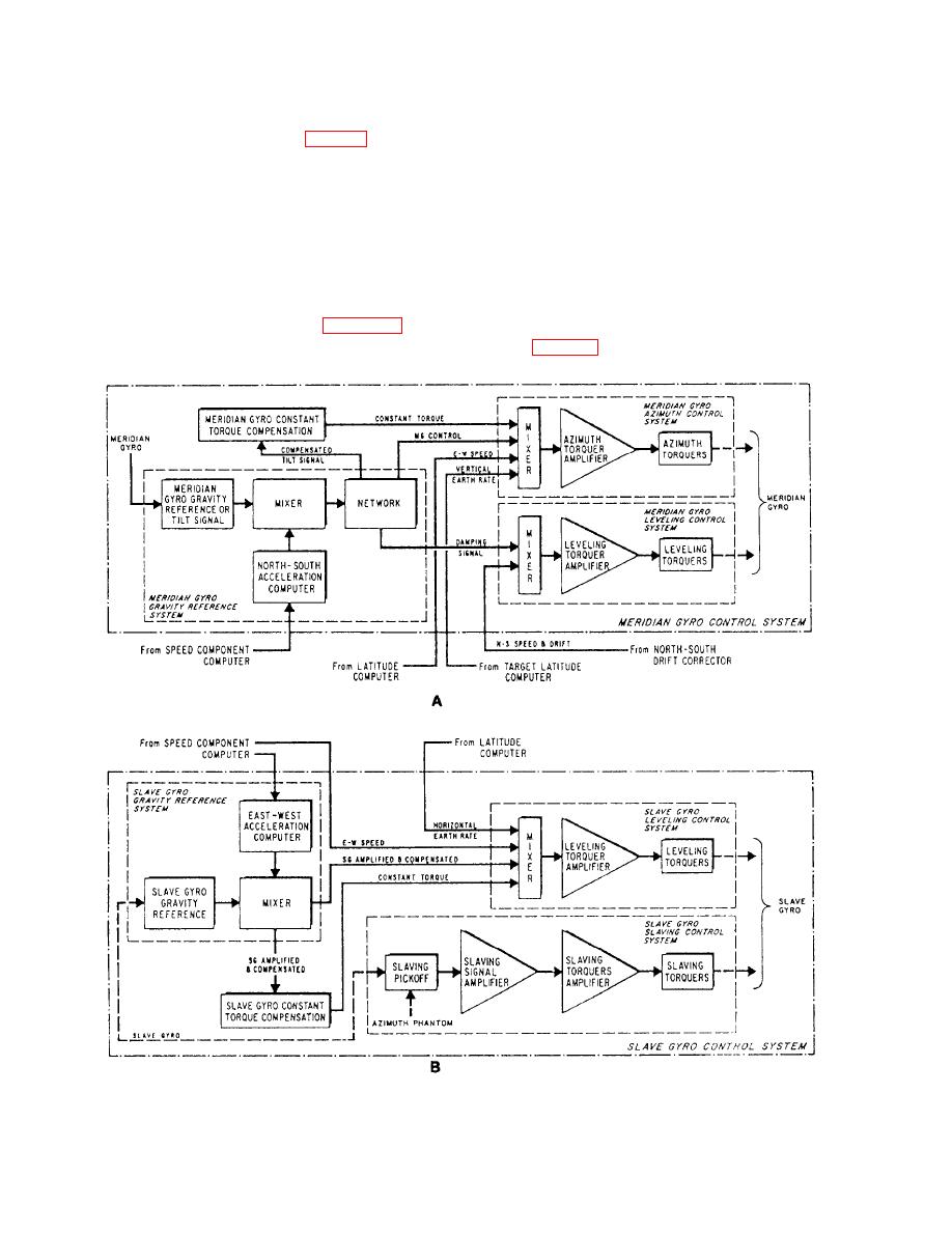
Figure 4-26.--A. Meridian gyro control system. B. Block diagram |
|
||
| ||||||||||
|
|
 On the bottom right-hand corner of the control
the compass system, for a short time, in case of failure
cabinet is a spare type 1 computer amplifier.
of the ship's power supply. Under normal operation the
ac section operates as a 115-volt, 400-Hz, 3-phase
Compass Failure Annunciator
synchronous motor, driving a 120-volt compound-
wound dc genemtor that charges a bank of 20 6-volt
The compass failure annunciator (fig. 4-20) is a remote
storage batteries. If the ship's 400-Hz supply fails, or
visual indicator, of the same type used in the Mk 23 system.
Associated with the annunciator is usually a Navy
falls below 105 volts, the ship's line is disconnected
standard type IC/B5DSF4 alarm bell. The alarm bell and
automatically and the 120-volt dc generator is driven as
annunciator are actuated by the alarm control system to
a motor by the storage batteries. The ac section now
give both a visual and audible indication of system failure.
operates as a 115-volt, 4(X)-Hz, 3-phase generator
The compass alarm system is discussed later in this chapter.
supplying the compass system.
Mk19 Mod 3A Gyrocompass Controls
Standby Power Supply
All controls for the Mk 19 Mod 3A gyrocompass
The standby power supply (fig. 4-20) is a
motor-generator set that provides emergency power for
system (fig. 4-26, views A and B) are contained in four
|
|
Privacy Statement - Press Release - Copyright Information. - Contact Us |