 |
|||
|
|
|||
| ||||||||||
|
|
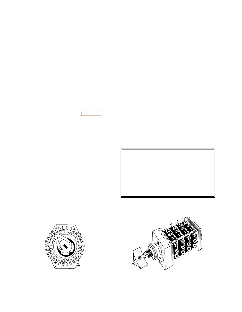 moving between positions. Open circuit problems have
forms over the contacts, which is only broken down if
been eliminated in this manner. The blade arrangement
appreciable voltage and power are available in the
provides for a circuit between two adjacent contacts,
circuit. However, in sound-powered telephone
such as in the 2JR switch previously discussed. The type
circuits, there is insufficient power to break down the
2JF has two such blade arrangements per switch deck.
film, and relatively high resistance results. The
The standard switches have one, three, and five switch-
silver-to-silver contacts of the JA switch consist of
ing decks, which are indicated in the type designation
pure silver welded to beryllium copper. Silver or
by the number following JF.
silver-coated contacts are now being used for the latest
The original production of the switches had a detent
type JA switches and other low-current switches. In
to limit the switching action to two positions. The
larger switches, silver (unless alloyed with other
present design has a 12-position detent arrangement
metals) is unsatisfactory because it vaporizes too
with adjustable stops. The stops can be adjusted
readily due to arcing.
by removing the four screws on the back plate and
The JA switch is available in two, six, and ten
arranging the stop arms mounted on the switch shaft to
sections. An example of the switch designation is
give the number of positions desired.
JA6C( 16) for a 6-section, 16-position switch; here the
An O-ring on the switch shaft within the mounting
first number designates the number of sections, the C
bushing prevents water from entering the switch. An
indicates common rotor, and the number in
O-ring is also provided on the outside of the mounting
parentheses indicates the number of positions.
bushing to give a watertight seal against the panel
in which the switch is mounted. These features have
eliminated the need for a watertight cover over the
developed primarily to replace toggle switches in the
switch.
10- and 20-switch boxes for sound-powered telephone
The JF switch is satisfactory for 120-volt ac
applications.
applications up to 1 ampere. It is being used in sound-
Because of the problems in making toggle
powered telephones, loudspeakers, microphone sta-
switches watertight, it was necessary to provide a
tions, and similar low-current equipment.
cover with a gasket for the 10- and 20-switch boxes,
which contained the toggle switches. The cover had to
CAUTION
be open when the switches were operated. Therefore,
the switch box was not watertight, leading to possible
The switch decks are made of molded
malfunctioning of the switches. In addition, the lack
nylon material. Be careful in soldering the leads
of a strong contact wipe action in toggle switches and
to the switch contacts. Too much heat passing
the low voltage and current in sound-powered circuits
back to the switch deck will destroy the switch
resulted in the formation of an insulating film on the
deck or damage the insulation between
contacts. This film resulted in open circuits or, if
adjacent contacts.
required, several operations of the toggle switch
handle before the circuit was initially made.
The JF switch replacement uses silver-to-silver
contact surfaces and provides a strong wiping action in
|
|
Privacy Statement - Press Release - Copyright Information. - Contact Us |
