 |
|||
|
|
|||
| ||||||||||
|
|
 bridges two adjacent contacts simultaneously (for
smaller than the J switch. This feature saves
example, contacts 1 and 2 when the switch is
switchboard space. This feature also makes
operated), the blade breaks contact 1 before making
disassembly a lot easier. Remember, however, that a
the next alternate contact 3 (for example, in the 2JR
faulty switch should be repaired only when immediate
replacement is not possible, and it should be replaced
switch, alternate terminals may be connected to an
independent source of ac power without danger of
at the earliest opportunity. The JR switch is divided
into four types: 1JR, 2JR, 3JR, and 4JR.
short circuit during movement of the switch blade).
Barriers are also provided between sections to
The 1JR switch has only one movable contact per
prevent terminals from turning and shorting to
section. This movable contact bridges two adjacent
adjacent terminals.
stationary contacts.
If the sections are not uniform, the switch will be
The 2JR switch has two movable contacts per
designated by JRSP followed by the number of
section, 180 apart. Each movable contact bridges two
sections.
adjacent stationary contacts.
The JR switch has a stop deck, which permits
The 3JR switch uses one of the stationary contacts
setting the switch to the number of positions desired.
as a common terminal. This stationary contact is
Pins or screws inserted in the stop deck immediately
connected, in turn, to each of the other stationary
after the desired last position will limit the switch
contacts of the section by a single-wiper contact. The
movement to the positions between these points.
3JR switch is used for selecting one of several (up to
TYPE JL.-- The JL switch is identical to the JR,
seven) inputs.
except in size, mounting facility, and electrical rating.
The diameter of the JL deck is approximately 1 3/4
The 4JR switch is designed as an either or both
inches, whereas the diameter of the JR deck is
switch with two movable contacts per section. Each
approximately 2 1/4 inches. The rating of the JL
movable contact bridges three adjacent stationary
switch is 120 volts, 60 Hz, 5 amperes. Standard types
contacts. This switch is used to select either or both of
are available in three, five, and ten sections. The JL
two indicators or synchros. The positions for
switch has a threaded bushing for single-hole
energizing two indicators are as follows:
mounting.
90 right--both indicators energized.
45 right--indicator 1 energized only.
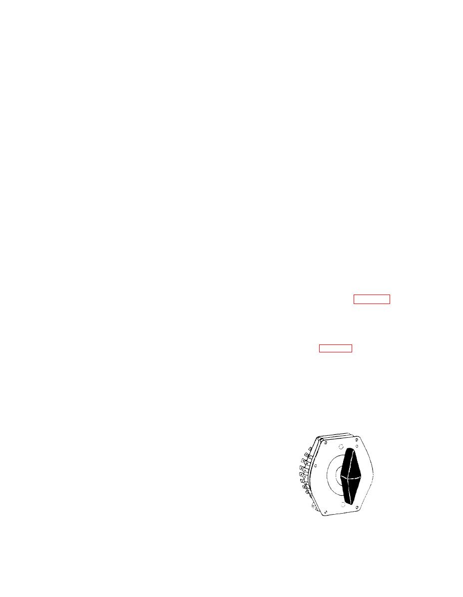
oped primarily for circuit selection in sound-powered
0--off.
telephone applications. It provides a greater number of
selections and is a smaller switch than the JR switch.
45 left--indicator 2 energized only.
The JA switch is furnished only with common rotor
When the 4JR switch is in the OFF position, both
sections (as shown in fig. 2-11). Sixteen-position and
indicators are connected together, but they are
30-position JA switches permit selection of 16 and 30
disconnected from the power supply.
circuits, respectively. With the JR switch, the maximum
number of possible selections is seven.
The designations of JR switches are determined
by the type of section (rotary and stationary contacts)
The JA switch also provides lower contact
followed by the number of sections in the switch. For
resistance by using either silver or silver-overlay
example, a 2JR10 switch denotes a JR switch with ten
contacts. With brass or copper, an insulating film
2JR sections.
The JR switch is stocked in multiples of five
sections (up to 25 sections). In some cases, a switch
with a number of sections (not a multiple of five) has
been installed. If this switch must be replaced, a switch
with the next largest number of sections that is a
multiple of five should be installed, if space permits.
Type JR switches are rated at 120 volts, 60 Hz, 10
amperes. The switch should not be used on dc circuits
because of the possibility of severely burned contacts
when the switch is operated slowly (teased). The
switch is the nonshorting type. Although the blade
2-6
|
|
Privacy Statement - Press Release - Copyright Information. - Contact Us |
