 |
|||
|
Page Title:
Figure 2-7.--Rotary selector switch. |
|
||
| ||||||||||
|
|
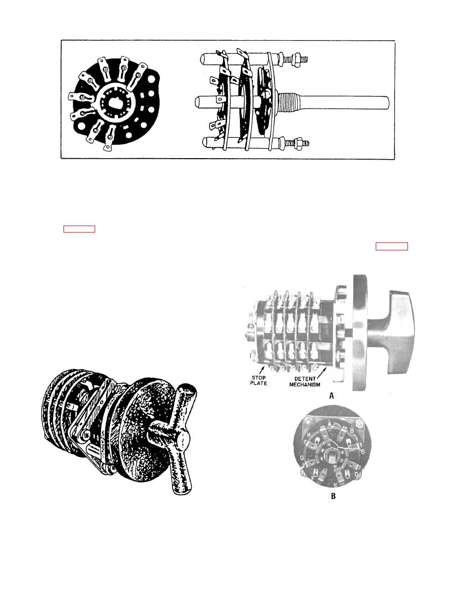 one position, the rotor contacts bridge segments A-
this type. These switches are more common in
B and E-F, in the next position, the rotor contacts
civilian equipment than in military hardware.
bridge segments B-C and F-G. Diagonally opposite
pairs of contacts are subsequently bridged for the
TYPE J.-- The type J multiple rotary selector
remaining positions.
switch (fig. 2-8) consists of an equal number of
rotors and pancake sections. The number of
sections required in the switch is determined by
installed on recent IC switchboards. This switch is
the individual application. A shaft with an
operating handle extends through the center of
the rotors. The movable contacts are mounted on
the rotors, and the stationary contacts are
mounted on the pancake sections. Each section
consists of eight contacts, designated A to H, and a
rotor with two insulated movable contacts spaced
180 apart. Each movable contact is arranged to
bridge two adjacent stationary contacts. The
switch has eight positions. A detent mechanism is
provided for proper alignment of the contacts
in each position of the operating handle. In
12.71
|
|
Privacy Statement - Press Release - Copyright Information. - Contact Us |
