 |
|||
|
|
|||
| ||||||||||
|
|
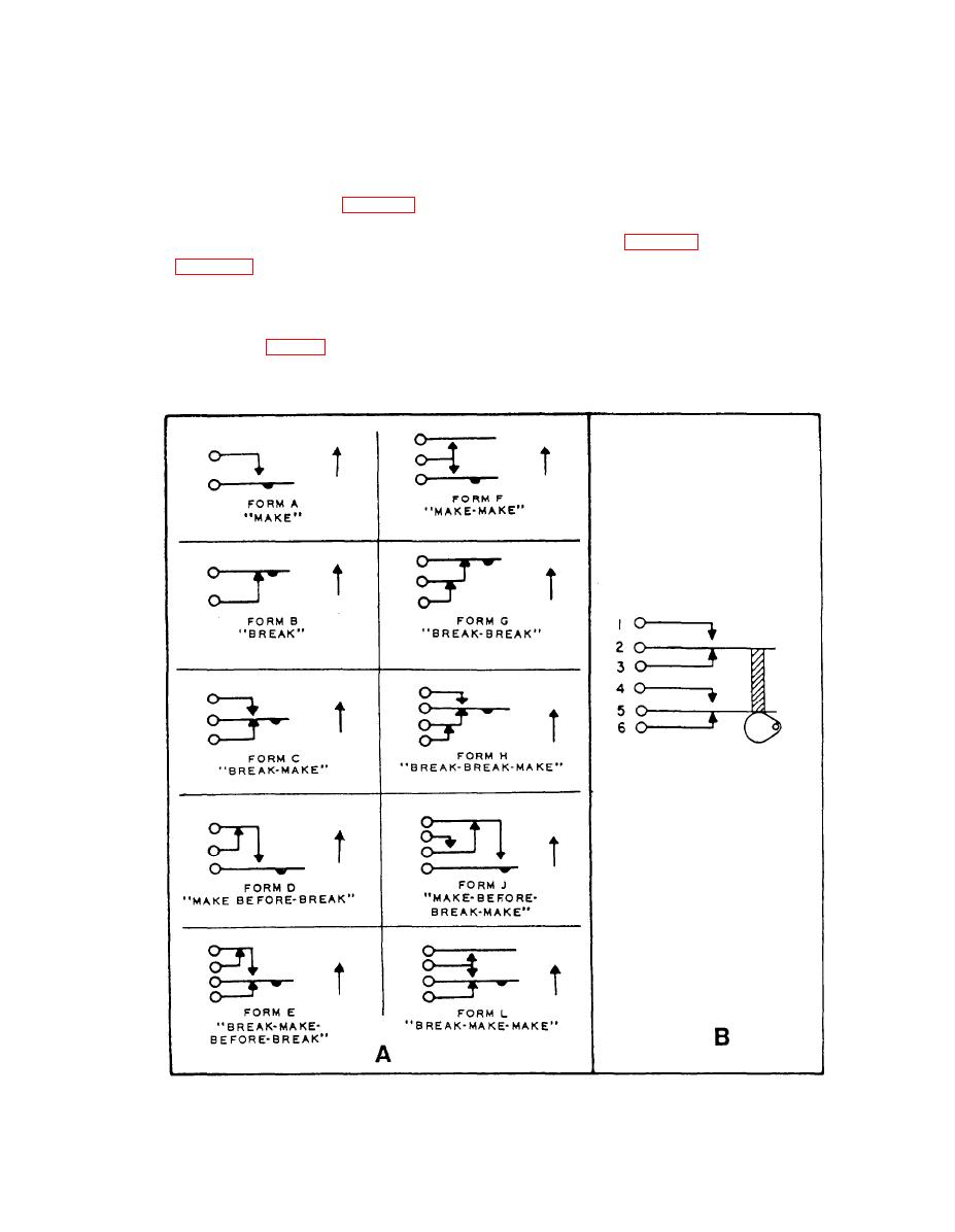 commonly used in relays, key switches, and jacks in
Pile Switches
low-voltage signal circuits.
Pile switches are constructed so they open or close
one or more electrical circuits. The contacts are
Rotary Selector Switches
arranged in leaf, or pileup, fashion and maybe actuated
by a rotary, pushing, or sliding motion.
Rotary selector switches may perform the functions
The various basic forms of the contact arrange-
of a number of switches. As the knob or handle of a
ments in pile switches are shown in figure 2-6, view A.
rotary selector switch is rotated, it opens one circuit and
These basic forms are used by themselves or in combi-
closes another. In figure 2-7, the contact is from A to E.
nation to makeup the contact assembly of a pile switch.
If the switch is rotated clockwise, as viewed, the circuit
View B of figure 2-6 shows a contact assembly made
from A to E is opened and the circuit from A to D
by combining two break-make contact arrangements to
is completed. Some rotary switches have several layers
make form C. This switch is, therefore, designated 2C.
of pancakes or wafers. With additional wafers, the
When the armature is moved upward by the rotary
switch can operate as several switches. Oscilloscope
motion of the cam lobe (fig. 2-6, view B), two circuits
and voltmeter selector switches are typical examples of
are opened and two are closed. This type of switch is
|
|
Privacy Statement - Press Release - Copyright Information. - Contact Us |
