 |
|||
|
Page Title:
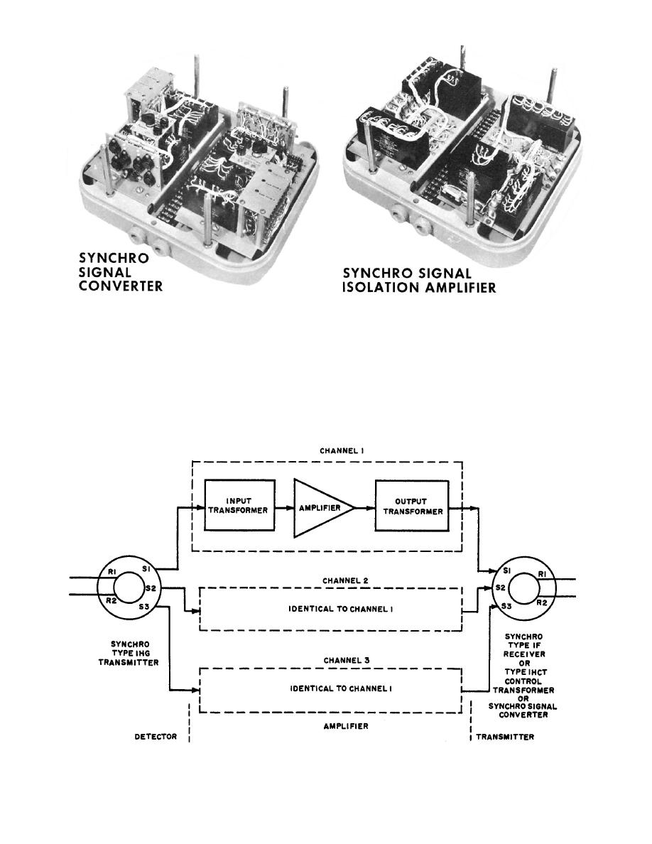
Figure 2-17---Simplified amplifier block diagram (direction or speed). |
|
||
| ||||||||||
|
|
 40.137
Figure 2-16.--Synchro signal converter and synchro signal isolation amplifier.
the input transformer. The signal is stepped down
one apply to the other. Each chassis consists of three
and fed into a transistor amplifier operating in the
channels that are the same in circuitry and
class B push-pull configuration.
operation; thus, the principles of operation of only one
channel will be explained. (See fig. 2-17.)
The input impedance of the amplifier is high, and
the output impedance is low. This condition prevents
The sine-wave output from the stator winding of an
external synchro is applied to the primary winding of
Figure 2-17---Simplified amplifier block diagram (direction or speed).
2-17
|
|
Privacy Statement - Press Release - Copyright Information. - Contact Us |
