 |
|||
|
Page Title:
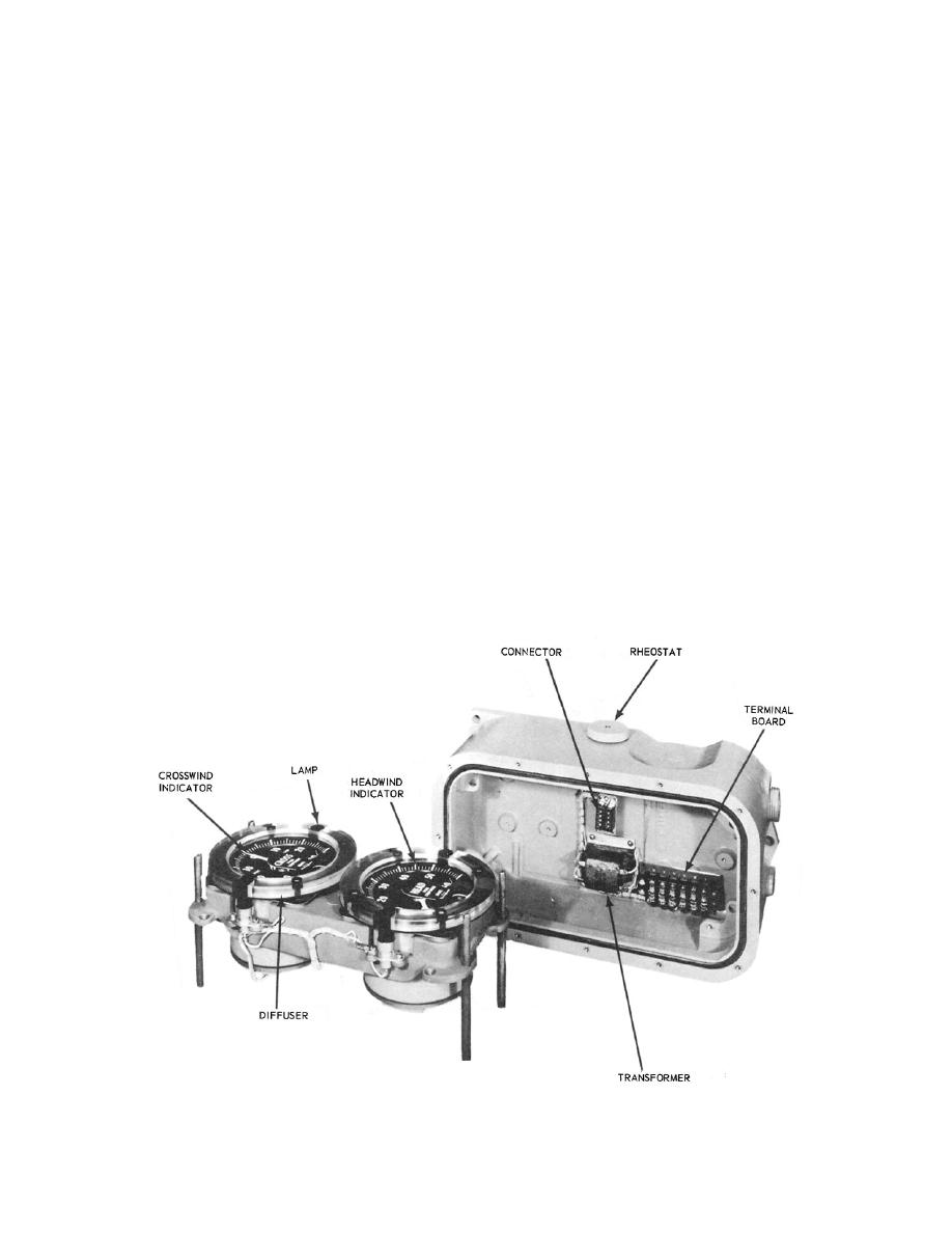
Figure 2-15.Indicator assembly. |
|
||
| ||||||||||
|
|
 INDICATOR
working with transistors and that they follow the
instructions in the proper technical manual. The
manufacturer has specified the use of certain meters
The crosswind component signals are applied to
for analyzing the condition of the components of the
the crosswind indicator of the indicator assembly
unit, and, where possible, these should be used.
(shown in fig. 2-15). The headwind component signal
is applied to the other indicator in the assembly. The
SYNCHRO SIGNAL CONVERTER AND
indicators have microammeter movements. The
SYNCHRO SIGNAL ISOLATION
headwind indicator is calibrated for 50 microampere
AMPLIFIER
full-scale deflection, which corresponds to 60 knots.
The dial reads from 0 to 60 knots in 1-knot
Another of the recent developments in the use of
increments. The crosswind indicator is calibrated for
25 microampere for full-scale deflection left and
synchro signal isolation amplifier shown in figure 2-
right. The crosswind scale reads from 30 knots port to
16.
30 knots starboard in 1-knot increments. The
rheostat on the assembly connects in series with the
The problem of retransmitting accurate wind
secondary of the line transformer and the
information devoid of error and unwanted feedback to
illuminating lamps, and is used to control their
the transmitter has existed for some time. The
intensity.
additional problem of conversion of a 60-Hz signal for
MAINTENANCE AND
use in computers is also not new. The synchro signal
TROUBLESHOOTING
isolation amplifier receives its signal from the wind
system and prepares it for the converter, allowing the
exact signal to be converted to 400 Hz.
The maintenance of this unit is outlined in the
appropriate PMS documents. The technical manual
ISOLATION AMPLIFIER
for
the
equipment
contains
an
adequate
troubleshooting chart. Therefore, there should be no
The amplifier contains two chassis that are the
difficulty in keeping the unit running. You should be
same, one for direction and one for speed. The
sure that personnel trying to repair the amplifier
principles of
units are familiar with the proper techniques for
40.135
Figure 2-15.Indicator assembly.
2-16
|
|
Privacy Statement - Press Release - Copyright Information. - Contact Us |
