 |
|||
|
Page Title:
Figure 2-18.--Simplifled converter block diagram (direction or speed). |
|
||
| ||||||||||
|
|
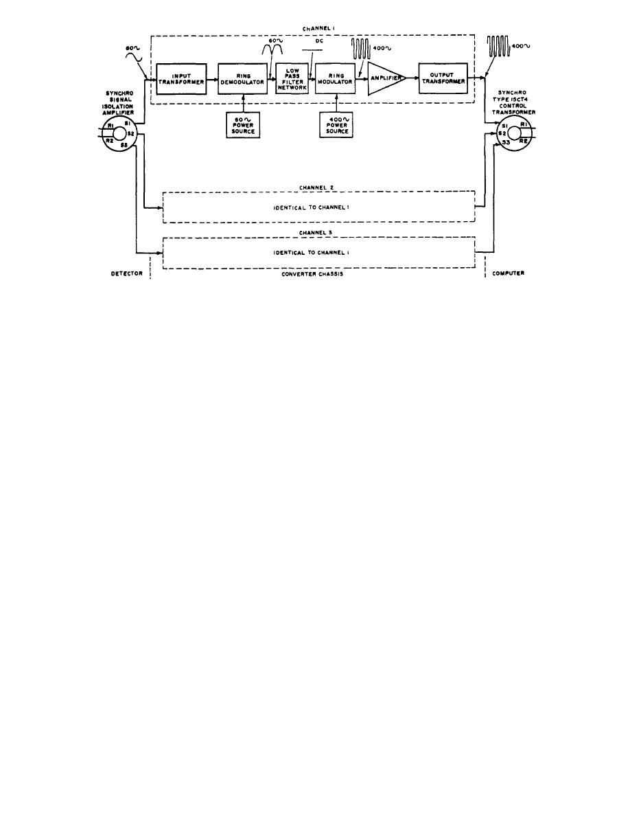 Figure 2-18.--Simplifled converter block diagram (direction or speed).
direct current at a level dependent upon the amplitude
phase differences between the input and output
of the signal voltage from the synchro stator.
synchros) from being reflected into the converter. The
amplified signal is transformed into sufficient amplitude
The dc signal is then fed into a ring-modulator stage
and is applied with the outputs of the two other channels.
that is excited by the voltage from a 400-Hz excitation
transformer. The output of the ring modulator is a
400-Hz sine wave with an amplitude proportional to the
CONVERTER
magnitude of the dc signal. Two power transistors
operating in the class B push-pull amplifies the 400-Hz
signal.
The converter also contains two chassis that are the
same, one for direction and one for speed. The principles
The amplified 400-Hz signal is sent through an
of operation of one apply to the other. Each chassis
output transformer that steps up the amplitude to 90
consists of three channels that are alike in circuitry and
volts, the required level for excitation of a type 15CT4
operation; thus, the principle of operation of only one
synchro control transformer.
channel is discussed. (See fig. 2-18.)
MAINTENANCE
The sine-wave output from one stator winding of an
external synchro or the synchro isolation amplifier is
applied to the primary winding of the input transformer
Once initially set up for proper operation, the
of the converter. The stepped down signal is sent to the
synchro signal converter and isolation amplifier unit
ring-demodulator stage. The ring-demodulator stage is
requires a minimum of maintenance. As with all
excited by the voltage from a 60-Hz excitation
transistorized units, heat can be a problem, and careful
transformer. The sine wave from the synchro is either in
selection of location is necessary.
phase or 180 out of phase with the excitation voltage.
Preventive maintenance should be limited to clean-
If the sine wave is in phase, the demodulated signal is a
ing all units periodically.
positive, pulsating dc voltage. If the sine wave is out of
Corrective maintenance requires the use of specific
phase, the demodulated signal is a negative, pulsating
metering, outlined in the manufacturer's technical man-
dc voltage. The pulsating dc voltage enters a low-pass
ual
filter network. The output of the filter network is pure
2-18
|
|
Privacy Statement - Press Release - Copyright Information. - Contact Us |
