 |
|||
|
Page Title:
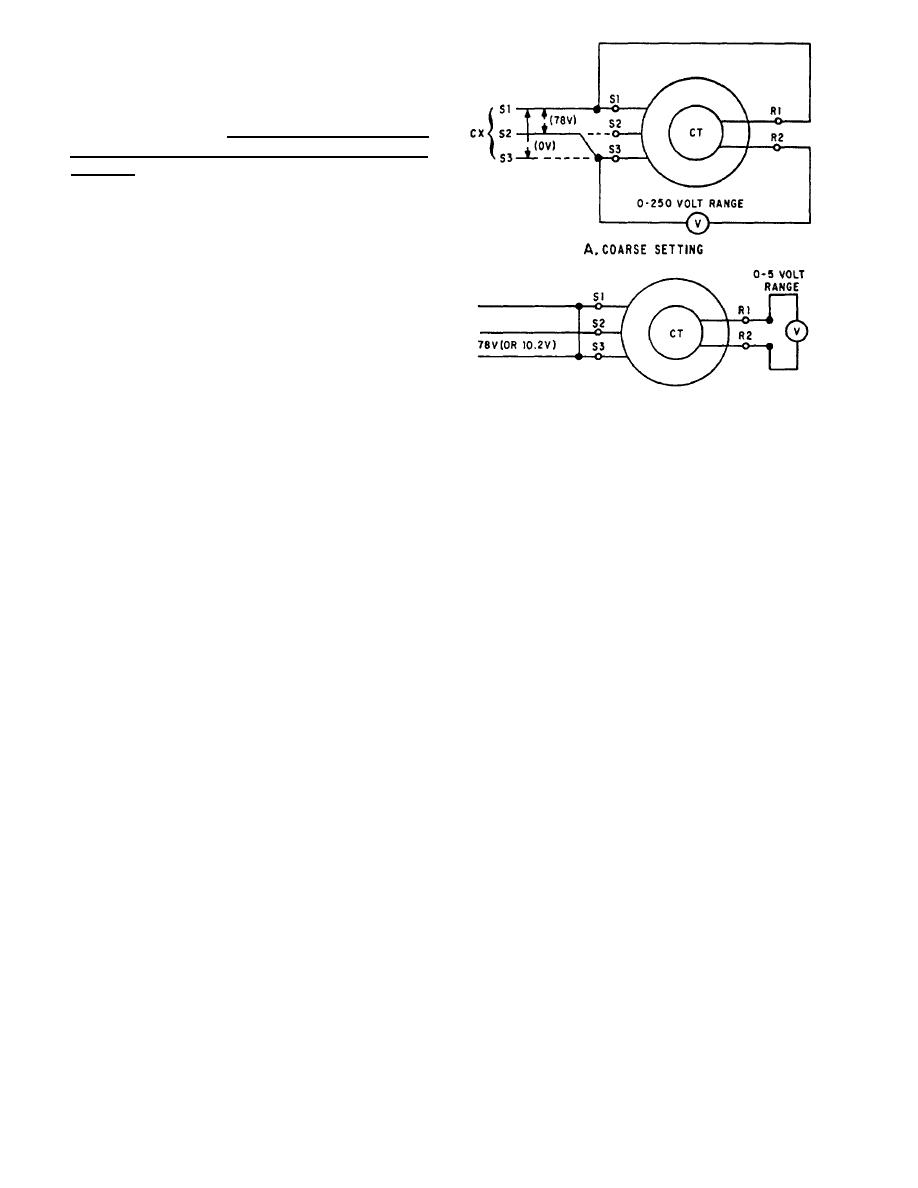
Figure 2-9.--Zeroing a control transformer by the voltmeter method. |
|
||
| ||||||||||
|
|
 2. De-energize the circuit and disconnect all other
connections from the differential leads. Set the volt-
meter on its 0- to 250-volt scale and connect as shown
in figure 2-8, view A. If a 78-volt supply is not available,
you may use 115 volts. If you use 115 volts instead of
78 volts, do not leave the unit connected for more than
2 minutes or it may overheat and may cause permanent
damage.
3. Energize the circuit, unclamp the differential's
stator, and turn it until the meter reads minimum. The
differential is now approximately on electrical zero.
De-energize the circuit and reconnect it as shown in
figure 2-8, view B.
4. Re-energize the circuit. Start with a high scale
on the meter and work down to the 0- to 5-volt scale to
protect the meter movement. At the same time, turn the
differential transmitter until a zero or null (minimum
voltage) reading is obtained. Clamp the differential
stator in this position, ensuring the voltage reading does
Figure 2-9.--Zeroing a control transformer by the voltmeter
not change, de-energize, and connect all leads for
method.
normal operation. This is the fine electrical zero position
of the differential.
ZEROING A CONTROL TRANSFORMER
exist for a control transformer (CT) to be on electrical
required to zero the CT, leave the S1 lead on, disconnect
zero. First, its rotor voltage must be minimum when
the S3 lead on the CT, and put the S2 lead (from CX) on
electrical zero voltages are applied to its stator. Second,
S3. This is necessary since 78 volts exist only between
turning the shaft of the CT slightly counterclockwise
S1 and S2 or S2 and S3 on a properly zeroed CX. Now
produces a voltage across its rotor in phase with the rotor
energize the circuit and turn the stator of the CT to obtain
voltage of the CX or TX, supplying excitation to its
a minimum reading on the 250-volt scale. This is the
stator. Electrical zero voltages, for the stator only, are
coarse or approximate zero setting of the CT.
the same as for transmitters and receivers.
4. De-energize the circuit, reconnect the S1, S2,
To zero a CT by the voltmeter method, use the
and S3 leads back to their original positions, and then
following procedure:
connect the circuit as shown in figure 2-9, view B.
1. Set the mechanism that drives the CT rotor to
5. Re-energize the circuit. Start with a high scale
zero or to its reference position. Also, set the transmitter
on the meter and work down to the 0-to 5-volt scale to
that is connected to the CT to zero or its reference
protect the meter movement. At the same time, turn the
position.
stator of the CT to obtain a zero or minimum reading on
the meter. Clamp down the CT stator, ensuring the
2. Check to ensure there is zero volts between S1
reading does not change. This is the fine electrical zero
and S3 and 78 volts between S2 and S3. If these voltages
position of the CT.
cannot be obtained, it will be necessary to rezero the
transmitter.
Zeroing Multispeed Synchro
NOTE: If 78 volts from the transmitter cannot be
Systems
used and an autotransformer is not available, use a
115-volt source. The CT should not be energized for
If multispeed synchro systems are used to
more than 2 minutes in this condition because it will
accurately transmit data, then the synchros within the
overheat and may cause permanent damage.
systems must be zeroed together. This is necessary
because these synchros require a common electrical
3. De-energize the circuit and connect the circuit
zero to function properly in a system.
as shown in figure 2-9, view A. To obtain the 78 volts
2-7
|
|
Privacy Statement - Press Release - Copyright Information. - Contact Us |