 |
|||
|
Page Title:
Figure 2-7.--Zeroing a transmitter or receiver by the voltmeter method. |
|
||
| ||||||||||
|
|
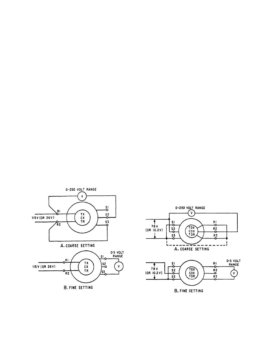 NOTE: Many synchro systems energize by
ZEROING TRANSMITTERS AND RECEIV-
individual switches. Therefore, be sure the synchro
ERS (VOLTMETER METHOD). A synchro
power is off before working on the connections.
transmitter, CX or TX, is zeroed if electrical zero
voltages exist when the device whose position the CX
3. Energize the synchro circuit and turn the stator
or TX transmits is set to its mechanical reference
or rotor until the meter reads about 37 volts (15 volts for
a 26-volt synchro). This is the coarse setting, and it
position. A synchro receiver, TR, is zeroed if, when
places the synchro at about electrical zero.
electrical zero voltages exist, the device actuated by the
receiver assumes its mechanical reference position. In a
4. De-energize the synchro circuit and connect the
receiver or other unit having a rotatable stator, the zero
meter as shown in figure 2-7, view B, using the 0- to
position is the same, with the added provision that the
5-volt scale.
unit to which the stator is geared is set to its reference
5. Re-energize the synchro circuit and adjust the
position. In the electrical zero position, the axes of the
rotor or stator for a null (minimum voltage) reading.
rotor coil and the S2 coil are at zero displacement and
This is the fine electrical zero position of the synchro.
the voltages measured between terminals S1 and S3 will
The common electrical zero position of a TX-TR
be minimum. The voltages from S2 to S1 and from S2
synchro system can be checked with a jumper. Put the
to S3 are in phase with the excitation voltage from R1
transmitter and receiver on zero and intermittently
to R2.
jumper S1 and S3 at the receiver. The receiver should
The following method may be used to zero
not move. If it does, the transmitter is not on zero and
transmitters and receivers:
should be checked again.
1. Carefully set the unit whose position the synchro
ZEROING DIFFERENTIAL SYNCHROS
transmits to its zero or mechanical reference position.
when it can be inserted into a system without intro-
2. De-energize the synchro circuit and disconnect
ducing a change in the system. In the electrical zero
the stator leads. Set the voltmeter to its 0- to 250-volt
position, the axes of coils R2 and S2 are at zero
scale and connect it into the synchro circuit as shown in
displacement. If a differential synchro requires zeroing,
figure 2-7, view A.
the following method may be used:
1. Carefully and accurately set the unit to be zeroed
to its zero or mechanical reference position.
Figure 2-8.--Zeroing differential synchros by the voltmeter
Figure 2-7.--Zeroing a transmitter or receiver by the voltmeter
method.
method.
2-6
|
|
Privacy Statement - Press Release - Copyright Information. - Contact Us |
