 |
|||
|
Page Title:
Figure 2-6.--Coarse eletrical zero markings. |
|
||
| ||||||||||
|
|
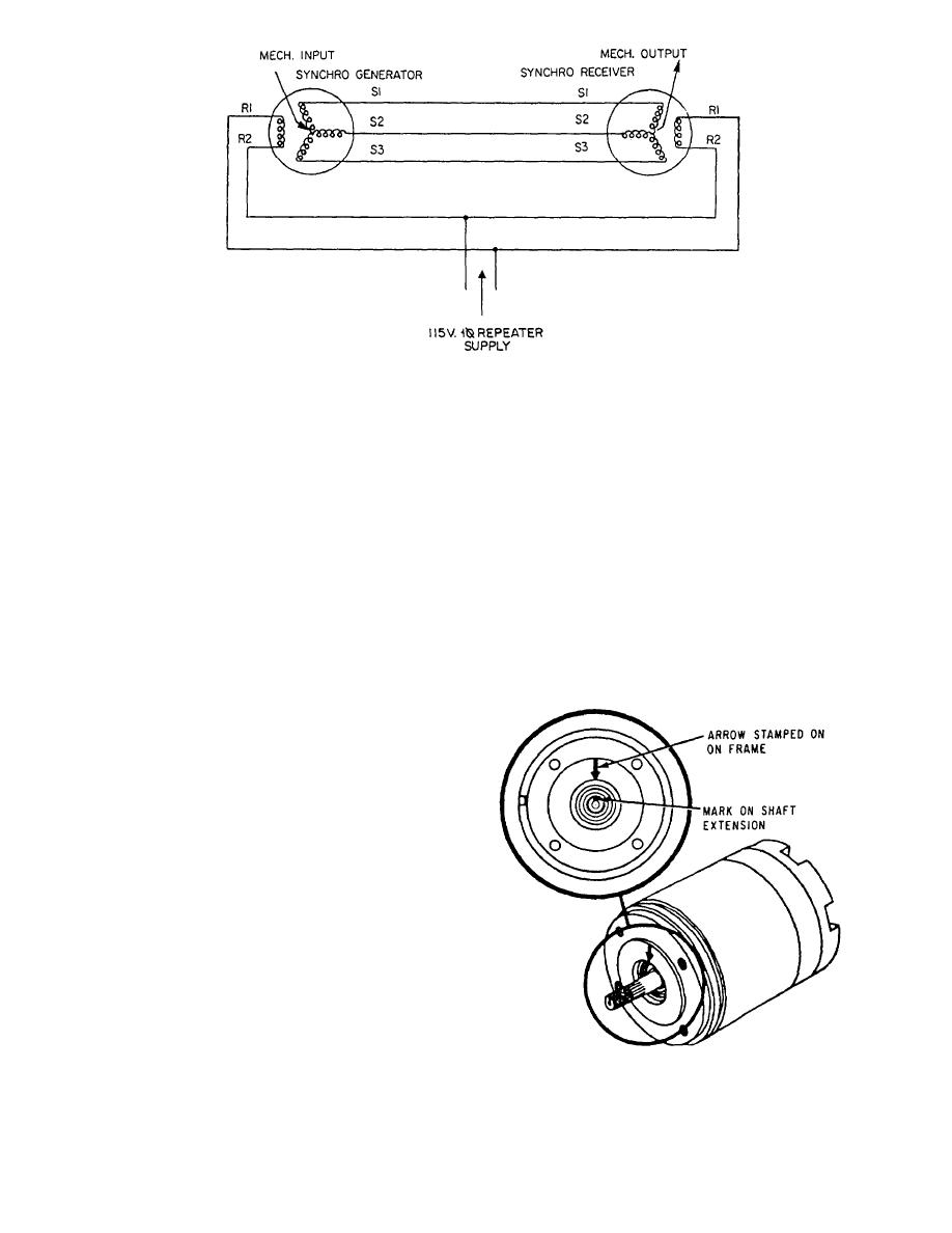 Figure 2-5.--Transmission system diagram; standard connections of a simple synchro.
Regardless of the synchro to be zeroed, there are
synchro units is electrical zero. The mechanical
reference point for the units connected to the synchros
two major steps in each procedure. The first step is the
depends upon the particular application of the synchro
coarse or approximate setting. The second step is the
system. Whatever the application, the electrical and
fine setting. The coarse setting ensures the device is
mechanical reference points must be aligned with each
zeroed on the 0 position rather than the 180 position.
other. The mechanical position is usually set first, and
Many synchro units are marked in such a manner that
then the synchro device is aligned to electrical zero.
the coarse setting may be approximated physically by
Each type of synchro has a combination of rotor position
aligning two marks on the synchro. On standard
and stator voltages that is its electrical zero.
synchros, this setting is indicated by an arrow stamped
There are various methods for zeroing synchros.
on the frame and a line marked on the shaft, as shown
Some of the more common zeroing methods are the
in figure 2-6. The fine setting is where the synchro is
voltmeter and the electrical lock methods. The method
precisely set on 0O.
used depends upon the facilities and tools available and
how the synchros are connected in the system. Also, the
method for zeroing a unit whose rotor stator is not free
to turn may differ from the procedure for zeroing a
similar unit whose rotor or stator is free to turn.
Voltmeter Method
The most accurate method of zeroing a synchro is
the ac voltmeter method. The procedure and the test-
circuit configuration for this method vary somewhat,
depending upon which type of synchro is being zeroed.
Transmitters and receivers, differentials, and control
transformers each require different test-circuit con-
figurations.
For the ac voltmeter method to be as accurate as
possible, an electronic or precision voltmeter having a
0- to 250-volt and a 0- to 5-volt range should be used.
On the low scale, this meter can also measure voltages
Figure 2-6.--Coarse eletrical zero markings.
as low as 0.1 volt.
2-5
|
|
Privacy Statement - Press Release - Copyright Information. - Contact Us |
