 |
|||
|
Page Title:
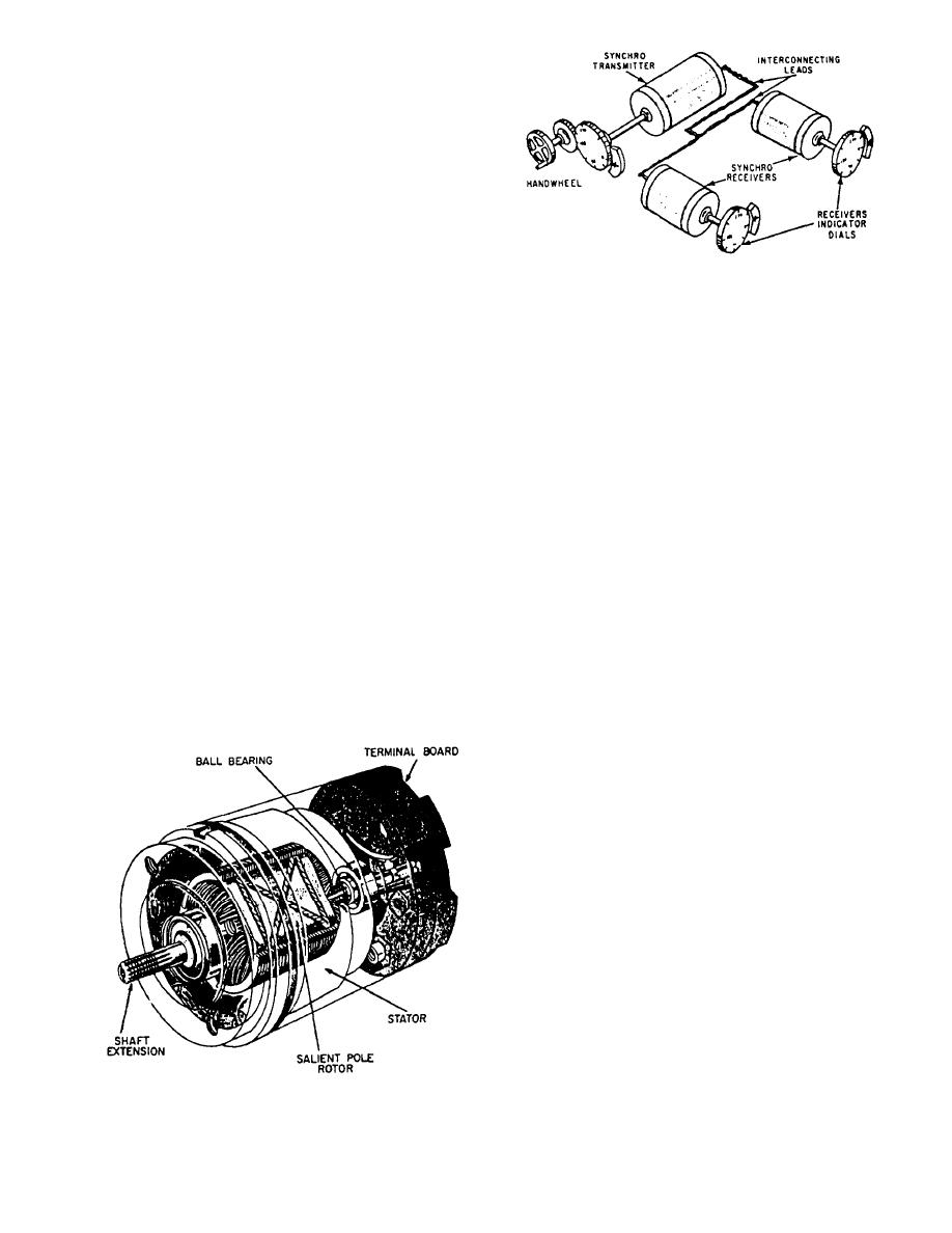
Figure 2-3.--Phantom view of a synchro. |
|
||
| ||||||||||
|
|
 in 5-knot intervals from 0 to 100 knots, covering 360.
A revolving pointer directly attaches to the shaft.
The dials and pointers are illuminated by red lights.
No lamps in parallel supplied from a 115/6-volt
transformer inside the housing provide dial illumination
for each assembly. A knob on the side of the case controls
a rheostat for varying the intensity of the illumination.
If the dials are indicating inaccurately, and you
decide to orient the speed and direction dials to a
different position, it will be necessary to zero the
Figure 2-4.--A simple synchro system.
synchros after the dials are repositioned. Zeroing
synchros is discussed later in this chapter.
Synchros (fig. 2-3) are used primarily for the rapid
NOTE: The type B indicator does not have dials that
and accurate transmission of information between
can be repositioned. Consider this fact when mounting
equipment and stations. Synchros are seldom used
the component.
singly. They work in teams, and when two or more
synchros are interconnected to work together, they form
The synchros in the indicator, either a 18TRX6 or
a synchro system. Such a system may, depending on the
18TRX4, electrically connect to the synchros in the
types and arrangement of its components, be put to
transmitter. The synchros in the indicator assume the
various uses. Figure 24 shows a simple synchro system
positions dictated by the transmitter synchros. The
that can be used to transmit different types of data.
pointers fastened to the rotor shafts of the synchros
indicate wind direction and windspeed on separate
STANDARD SYNCHRO CONNECTIONS
circular dials.
In systems in which a great many synchro units are
used, it is necessary to have a closely defined set of
SYNCHROS
standard connections to avoid confusion. The conven-
tional connection is for counterclockwise rotation for an
In performing the required PMS and maintenance
increasing reading.
on wind direction and indicating systems and on synchro
signal amplifiers (discussed later in this chapter), you
The standard connections of a simple synchro
should have an understanding of synchros. The follow-
transmission system consisting of a synchro transmitter
ing paragraphs will discuss synchros and the zeroing of
and receiver is shown in figure 2-5. The R1 transmitter
synchros.
and receiver leads connect to one side of the 115-volt ac
supply line. The R2 transmitter and receiver leads con-
nect to the other side of the line. The stator leads of both
the transmitter and receiver connect lead for lead; that
is, S1 connects to S1, S2 to S2, and S3 to S3. Thus, when
sending an increasing reading over the transmission
system, the rotor of the synchro receiver will turn in a
counterclockwise direction.
When it is desired, the shaft of the synchro receiver
turns clockwise for an increasing reading. The R1 and
R2 transmitter and receiver leads connect as before. The
S1 transmitter lead connects to the S3 receiver lead, and
the S2 transmitter lead to the S1 receiver lead.
If synchros are to work together properly in a
system, they must be correctly connected and aligned in
respect to each other and to the other devices with which
Figure 2-3.--Phantom view of a synchro.
they are used. The reference point for alignment of all
2-4
|
|
Privacy Statement - Press Release - Copyright Information. - Contact Us |
