 |
|||
|
|
|||
| ||||||||||
|
|
 the vane, the rotor on the synchro (directly coupled to
the vane) moves angularly a like amount. The angular
position of the type 18CX4 synchro is sent electrically
to a 18CT4 synchro in the direction assembly of the
transmitter and/or to computers.
Windspeed is determined by the speed of the rotor
assembly. The rotor assembly is held directly into the
wind by the vane assembly. Speed of rotation of the rotor
assembly is proportional to the speed of the wind
striking the blades.
Transmitter
The transmitter consists of two plug-in assemblies,
a direction assembly and a speed assembly. The assem-
blies are housed in a common, dripproof case designed
for bulkhead mounting.
The direction assembly is essentially a servo-
amplifier circuit using a type 18CT4 synchro control
transformer as a receiver for angular displacement sig-
nals representing the position of the vane. The purpose
of the direction assembly is to receive a 400-Hz signal
equivalent to a change in the position of the vane as sent
by the detector and to send this change at a pre-
determined rate, in the form of 60-Hz and 400-Hz
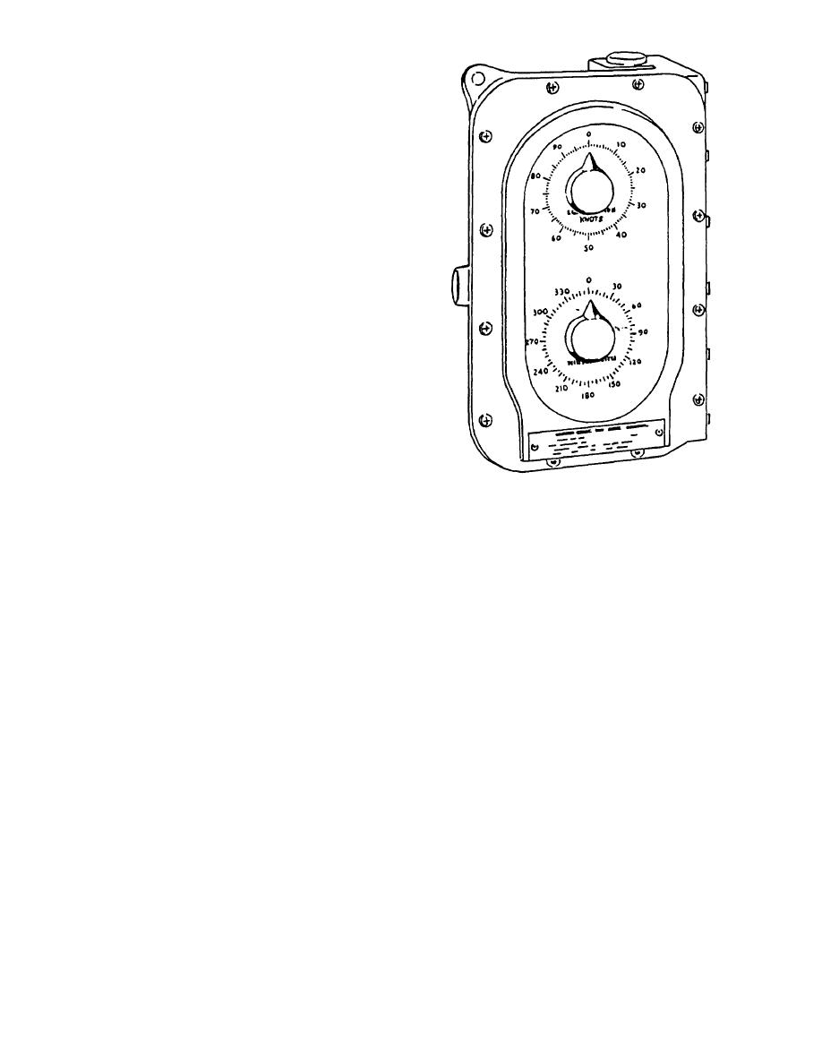
Figure 2-2.--Wind indicator.
synchro signals, to the indicators and/or recorders.
with the exception of their graduated dials, and are
The speed assembly consists of a servo-amplifier
housed in a watertight case, therefore eliminating con-
circuit and a roller disc-type integrator. The servo amp
sideration of the elements when determining location.
lifier uses a type 18CT4 synchro control transformer as
a receiver for signals from the detector representing the
The design of the wind indicating equipment, type
rotating speed of the rotor assembly. The purpose of the
F, allows for the use of a type B indicator with the system
speed assembly is to receive a signal equivalent to a
if so desired. The mounting for both types of indicators
change in rotational speed of the rotor assembly as sent
are basically the same. The selected indicator should be
by the detector, to amplify the signal, and to transmit
mounted on a bulkhead or stationary surface, according
this change at a linear rate, in the form of 60-Hz and
to the applicable dimensions. The location selected will
400-Hz synchro signals, to indicators and/or recorders.
depend upon the intended use of the indicator and the
convenience for wiring and servicing.
The direction assembly and the speed assembly are
basically a servo unit made up of a synchro control
The assemblies mount on individual baseplates. The
transformer, a followup motor, and a synchro
assemblies and baseplates are enclosed in a metal hous-
transmitter.
ing to form a complete wind direction and speed
indicator unit.
The transmitter should be mounted in a location that
is convenient for wiring and servicing. Consideration
The direction synchro receiver receives the angular
for protection from the elements is important, as the case
displacements from the synchro transmitter in the
is dripproof but not waterproof. Ensure the case is
direction assembly of the transmitter unit and indicates
grounded
these displacements on the direction dial. The direction
dial is graduated in 10 intervals from 0 to 360.
Indicator
The speed synchro receiver receives the angular
displacements from the synchro transmitter in the speed
The wind direction and speed indicator (fig. 2-2) is
assembly of the transmitter unit and indicates these
a dual unit consisting of a wind direction assembly and
displacements on the speed dial. The dial is graduated
a windspeed assembly. The two assemblies are the same,
2-3
|
|
Privacy Statement - Press Release - Copyright Information. - Contact Us |