 |
|||
|
Page Title:
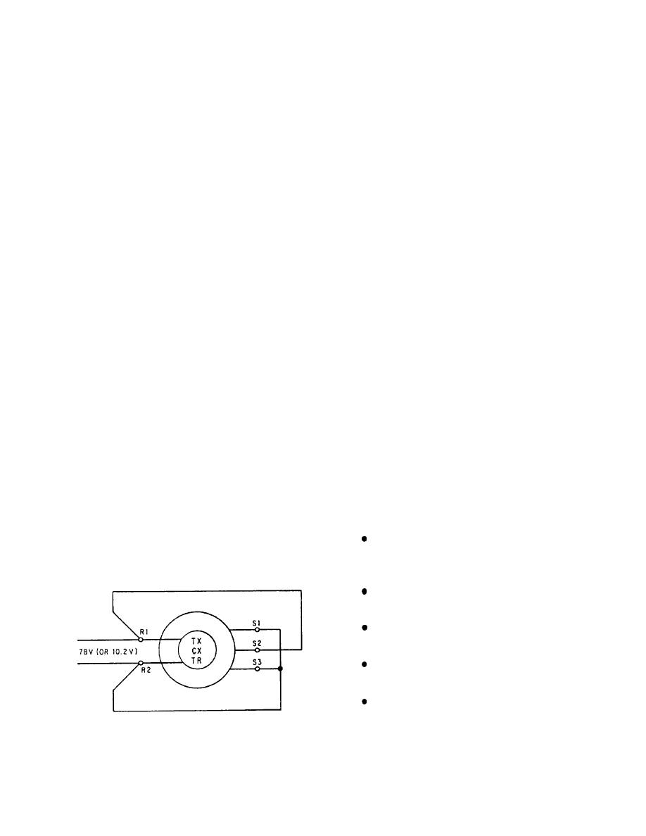
Figure 2-10.--Zeroing a synchro by the electrical lock method. |
|
||
| ||||||||||
|
|
 holes into its frame, NEVER use pliers on the threaded
First, establish the zero or reference position for the
unit whose position the system transmits. Then, zero the
shaft, and NEVER use force to mount a gear or dial on
most significant synchro in the system and work down
the shaft.
to the least significant. For example, zero the coarse
In maintaining synchros, there are two basic rules
synchro, then the medium synchro, and finally the fine
to apply:
synchro. When zeroing these synchros, consider each
synchro as an individual unit and zero accordingly.
1. IF IT WORKS, LEAVE IT ALONE.
There are a few 3-speed synchro systems. These
2. IF IT GOES BAD, REPLACE IT.
systems require zeroing in an identical reamer as the
Shipboard synchro troubleshooting is limited to
dual-speed systems. First, zero the most significant
determining whether the trouble is in the synchro or in
synchro in the system and then work down to the least
the system connections. You can make repairs to the
significant.
system connections, but if something is wrong with the
Remember that all synchros in a system must have
unit, replace it.
a common electrical zero position.
Electrical Lock Method
SYNCHRO SIGNAL AMPLIFIER
The electrical lock method (although not as accurate
The reason for using synchro signal amplifiers is to
as the voltmeter method) is perhaps the fastest method
reduce the size of synchro transmitters. These smaller
of zeroing synchros. However, this method can be used
synchro transmitters are used in wind indicators and
only if the rotors of the units to be zeroed are free to turn
other sensing devices that are more accurate if there is
and the lead connections are accessible. For this reason,
only a small load on their outputs.
this method is usually used on the TR because, unlike
You should already know the operating principle of
transmitters, the TR shaft is free to turn.
the synchro signal amplifier. The input to the amplifier
To zero a synchro by the electrical lock method,
is from a small synchro transmitter or two small trans-
de-energize the unit, connect the leads, as shown in
mitters that give a coarse and a fine signal. The input
figure 2-10, and apply power. The synchro rotor will
signal controls a small servomotor. This servomotor
then quickly snap to the electrical zero position and lock.
drives one or more large synchros into a position cor-
As stated before, you may use 115 volts as the power
responding to the position of the input synchro. The
supply instead of 78 volts if the unit does not remain
connected for more than 2 minutes.
output from the large synchros is then used as needed to
drive several synchro receivers.
SYNCHRO MAINTENANCE AND
Synchro signal amplifiers must meet some or all of
TROUBLESHOOTING
the following operational requirements:
Synchro units require careful handling at all times.
Accept a low-current synchro signal, amplify the
NEVER force a synchro unit into place, NEVER drill
signal, and use the amplifier signal to drive large-
capacity synchro transmitters.
Isolate oscillations in a synchro load that may be
reflected from the input signal bus.
Permit operation of a 60- or 400-Hz synchro load
from either a 60-or 400-Hz synchro bus.
Provide multiple charnel output transmission of
a single-channel input signal.
Permit operation of a synchro load independent
of the input synchro excitation.
A block diagram of a synchro signal amplifier is
Figure 2-10.--Zeroing a synchro by the electrical lock method.
shown in figure 2-11.
2-8
|
|
Privacy Statement - Press Release - Copyright Information. - Contact Us |