 |
|||
|
Page Title:
Figure 1-44.-Voltage regulator, simplified schematic. |
|
||
| ||||||||||
|
|
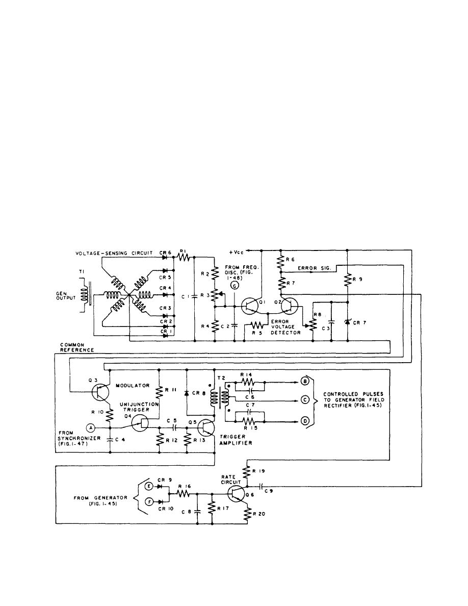 applied via R8, which is a factory set and locked
Voltage-Sensing Circuit
reference voltage adjustment.
The voltage-sensing circuit (fig. 1-44) steps down
Resistor R9 is the voltage dropping resistor for CR7,
the 3-phase generator 440-volt ac output through volt-
and capacitor C3 reduces the ripple and noise voltages
age-sensing transformer T1 to 25-volt ac. Each phase is
across CR7 to provide a clean dc reference voltage.
rectified by diodes CR1 through CR6 and filtered by C1
Resistors R6 and R7 are load resistors for transistor Q2.
and C2. This dc voltage is proportional to the generator
Any difference between the input voltage at the base
output voltage. The dc voltage is applied to voltage
of Q1 and the reference voltage at the base of Q2 will
divider network R1 through R4 (R3 can be adjusted to
produce an error signal (a change in collector current).
develop the amount of voltage desired as the
If the input voltage is higher than the reference voltage,
representative generator output) for comparison to the
Q1 conducts heavier than Q2 and vice versa when the
reference voltage in the error voltage detector circuit.
reference voltage is higher than the input. The voltage
drop across R6 is the error voltage that is applied to the
base of the modulator Q3.
Error Voltage Detector Circuit
Modulator Circuits
Transistors Q1 and Q2 (fig. 1-44) forma differential
amplifier to compare the base voltages of the two
transistors. The signal from the voltage-sensing circuit
The modulator circuit (fig. 1-44) modifies the time
is applied to the base of Q1, while the reference voltage
constant of the RC circuit (C4, R10, and the Q3
collector-emitter resistance). (The collector-emitter
is applied to the base of Q2. The reference voltage is
Figure 1-44.-Voltage regulator, simplified schematic.
1-40
|
|
Privacy Statement - Press Release - Copyright Information. - Contact Us |
