 |
|||
|
Page Title:
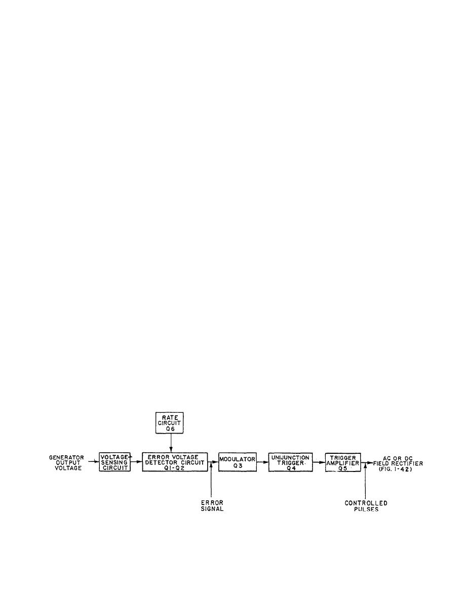
Figure 1-43.-Voltage regulator, block diagram. |
|
||
| ||||||||||
|
|
 GAP when the input frequency drops below 56 Hz or
energized. When the delay relay energizes (relay #2), it
applies normal power to the ac field rectifier, via the ac
the input voltage falls below an adjustable limit (330 to
voltage regulator, for application as field excitation to
380 volts).
the ac motor to allow synchronous motor operation. At
The voltage monitor circuitry is basically the same
the same time, the dc generator is rerouted to the dc
as the voltage-sensing and error voltage detector circuit
supply (relay #3) to prevent starting the motor-generator
of the voltage regulator. The frequency monitor is
set on dc and to charge the batteries. The system is now
basically the same as the frequency discriminator and
operating in NORMAL mode.
error voltage detector circuits. These circuits will be
If the normal supply falls out of its limits in either
discussed later in this chapter. The big difference in the
voltage or frequency, the respective monitor will sense
circuits is the output application. The output of the
it, and relay action (relay #4) will shut down the motor-
monitors is used for relay switching, since the other
generator set. At the same time, the dc generator field is
disconnected from the dc field rectifier #2 and con-
circuit's output is for regulation of either voltage or
nected directly to the battery supply (relay #5). The dc
frequency.
motor speed regulator and the ac generator voltage
regulator are energized (relay #6 and #7) to maintain the
VOLTAGE REGULATOR
required motor speed and control the load voltage. The
system is now in the STOP GAP mode.
The function of the voltage regulator is to maintain
If the reason for switching modes had been a voltage
the output voltage at the preset value (2 percent) regard-
drop, the voltage would not have dropped below 317
less of temperature or load variations. The basic cir-
volts, and the transition would have been accomplished
cuitry for both the ac and dc regulators is similar except
within 1 second. In the case of a frequency drop, the
that the dc regulator does not use the 6-phase rectifiers
change is made within 2 seconds and the frequency does
in the sensing circuit. Constant generator voltage output
not drop below 54 Hz.
is obtained by having the regulating circuit change the
When the ship's power returns to the specified
voltage feed in response to an error signal.
limits, the synchronizer will have the normal power at
one side and the ac generator power at the other. It will
A differential amplifier is used in the error voltage
automatically adjust the speed regulator to match the
detector circuit (fig. 1-43) to compare the generator
generator frequency to the normal power. The matching
output voltage, with a reference voltage, to produce the
is accomplished in less than 1 minute, and the system is
error signal. The error signal, acting through the
transferred back to ac motor drive and battery charge
modulator, modifies the timing of the pulse repetition
(NORMAL mode).
frequency of the unijunction trigger circuits. The
controlled pulses are fed to the respective field rectifier
MONITOR CIRCUITS
to control the average power to the generator field. The
rate circuit modifies the error signal to stabilize the
The frequency and voltage monitoring circuits are
designed to switch and set from NORMAL to STOP
voltage regulator.
Figure 1-43.-Voltage regulator, block diagram.
1-39
|
|
Privacy Statement - Press Release - Copyright Information. - Contact Us |
