 |
|||
|
Page Title:
Figure 1-42.-No-break "uninterrupted" power supply system, block diagram. |
|
||
| ||||||||||
|
|
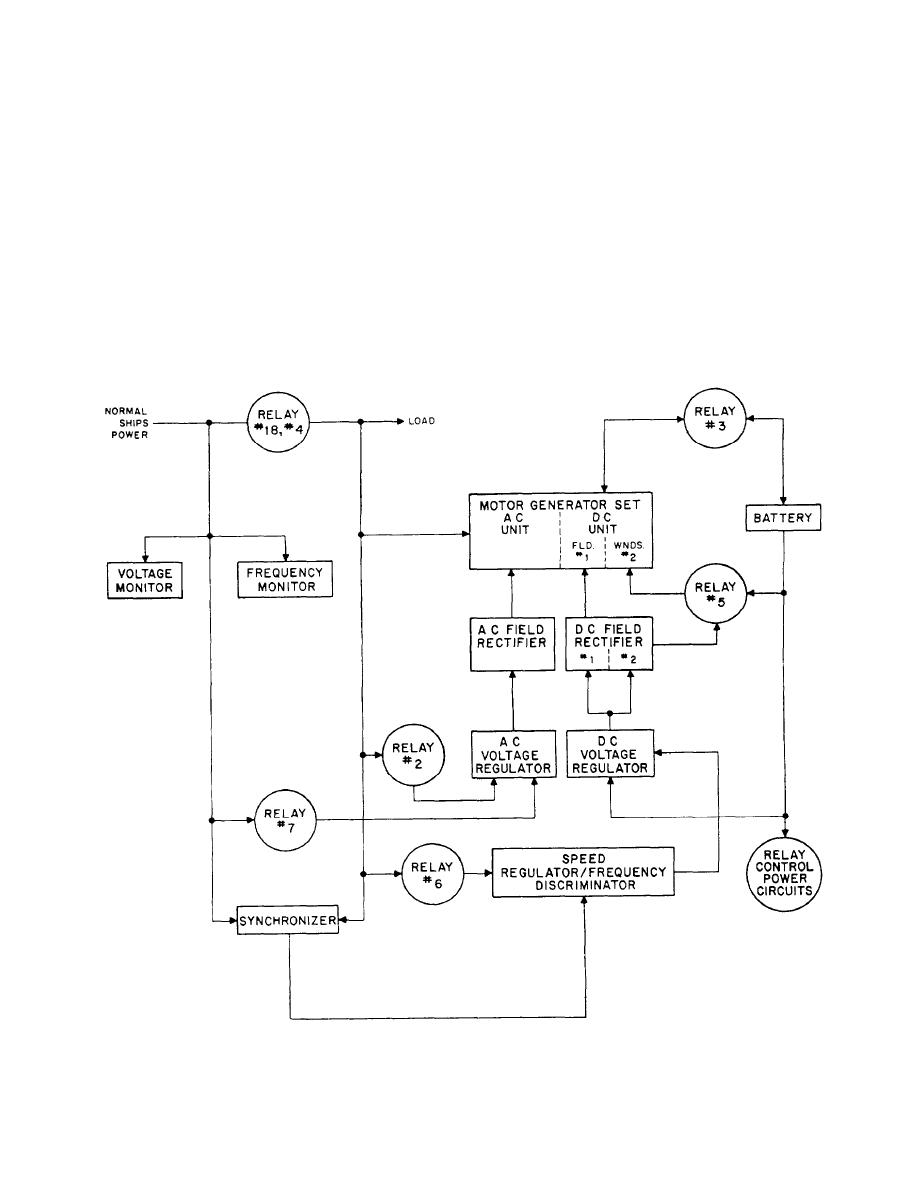 OPERATION
The control cabinet contains all the control and
monitoring equipments. The motor generator is a single-
Normal ship's power (fig. 1-42) is applied to the
shaft unit. Either section of the motor generator can
voltage and frequency monitors. If the monitors sense
perform as the motor with the other as the generator.
the normal power to be within the frequency and voltage
This permits two operational modes: NORMAL and
limits required relay action (relay #1) will allow the
STOP GAP.
normal power to be applied to the load and other cir-
NORMAL operation uses the normal supply (ship's
cuitry. (It should be noted that the relay numbers in
generators). The motor generator is driven by the ac
fig. 1-41 refer to relay action sequence rather than relay
motor from the ship's supply, and the dc generator
designations.) Power is applied to the relay control
charges the batteries.
power circuit from the battery.
In STOP GAP operation, the motor generator is
When the system is turned on, the motor generator
driven by the dc motor with power from the batteries.
will accelerate to approximately synchronous speed
Under this condition the ac generator provides power to
as an induction motor before a time delay relay is
the critical load.
Figure 1-42.-No-break "uninterrupted" power supply system, block diagram.
1-38
|
|
Privacy Statement - Press Release - Copyright Information. - Contact Us |
