 |
|||
|
Page Title:
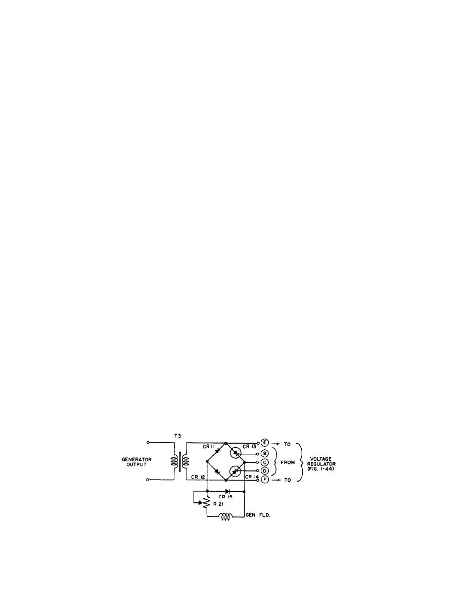
Figure 1-45.-Generator field rectifier, simplified schematic. |
|
||
| ||||||||||
|
|
 resistance is controlled by the current through resistor
relaxation oscillator that initiates controlled rate pulses
R6.) An increase in the error signal across R6 decreases
to trigger the field rectifiers. Q4 turns on when the
the collector-emitter resistance of Q3 and thus decreases
voltage across C4 and the emitter current of Q4 reach
the charge time of C4. If the error signal increases, the
preset values. When Q4 conducts, trigger pulses are
charge time of C4 is increased.
applied to the trigger amplifier Q5.
Capacitor C4 discharges when the voltage across it
is approximately 9 volts (the peak point voltage of
Trigger Amplifier Circuit
unijunction transistor Q4).
A synchronizing circuit (discussed later) clamps C4
The trigger amplifier (fig. 1-44) amplifies and
to ground, thus delaying the RC time cycle. A rate
shapes the trigger pulses. The circuit is a common
feedback signal is also applied by the rate circuit to the
emitter amplifier with RC input (R13 and C5) and
collector of Q2. This signal modifies the error signal,
transformer output (T2).
thus stabilizing the voltage regulator.
Transistor Q5 is protected against the inductive
kickback voltage of T2 by diode CR8. Resistors R14 and
Rate Circuit
R15 with capacitors C6 and C7 include a pulse-shaping
network to prolong the life of the SCRs in the field
The function of the rate circuit is to dampen the
rectifier.
generator output voltage distortion about a set point.
Otherwise, the high gain of the voltage regulator would
GENERATOR FIELD RECTIFIER
cause the generator output voltage to hunt. The method
used for damping the voltage distortion is feeding back
an inverted signal (opposite to the error signal),
Both the ac and dc field rectifiers are similar in
proportional to the rate of voltage change.
operation. The function of the generator field rectifier is
to provide controlled dc power to the generator field to
The rate circuit (fig. 1-44) consists of a common
regulate the generator input voltage with the field power
emitter amplifier (Q6, R19, and R20) and an integrating
being proportional to the conduction line of the SCRs.
circuit (R16 and C8). Resistor R17 is a discharge resistor
for C8, and CR9 and CR10 are common rectifiers.
Transformer T3 (fig. 1-45) transfers voltage from
the generator that is rectified by the bridge rectifier
The input is supplied by the generator field rectifier
(CR11 through CR14). The conduction of the bridge is
(described later), integrated, and applied as forward bias
controlled by SCRs, CR13, and CR14. One series
to the base of Q6. Any change in the base is amplified
combination of diode and SCR (CR11, CR13, or CR12,
and passed by C9 to the collector of the error detector,
CR14) may conduct for alternate half cycles. The dc
Q2. As this signal is opposite to the error signal, it will
output is the controlled generator field power.
decrease conduction and stabilize the circuit.
Diode CR 15 is used as an inductive kickback diode
Unijunction Trigger Circuit
to provide a path for the current generated by the
collapsing magnetic field of the generator during the idle
The trigger function is performed by the unijunction
portion of each cycle. The amount of field power can be
trigger circuit (fig. 1-44). Unijunction transistor Q4 is a
adjusted by R21.
Figure 1-45.-Generator field rectifier, simplified schematic.
1-41
|
|
Privacy Statement - Press Release - Copyright Information. - Contact Us |
