 |
|||
|
Page Title:
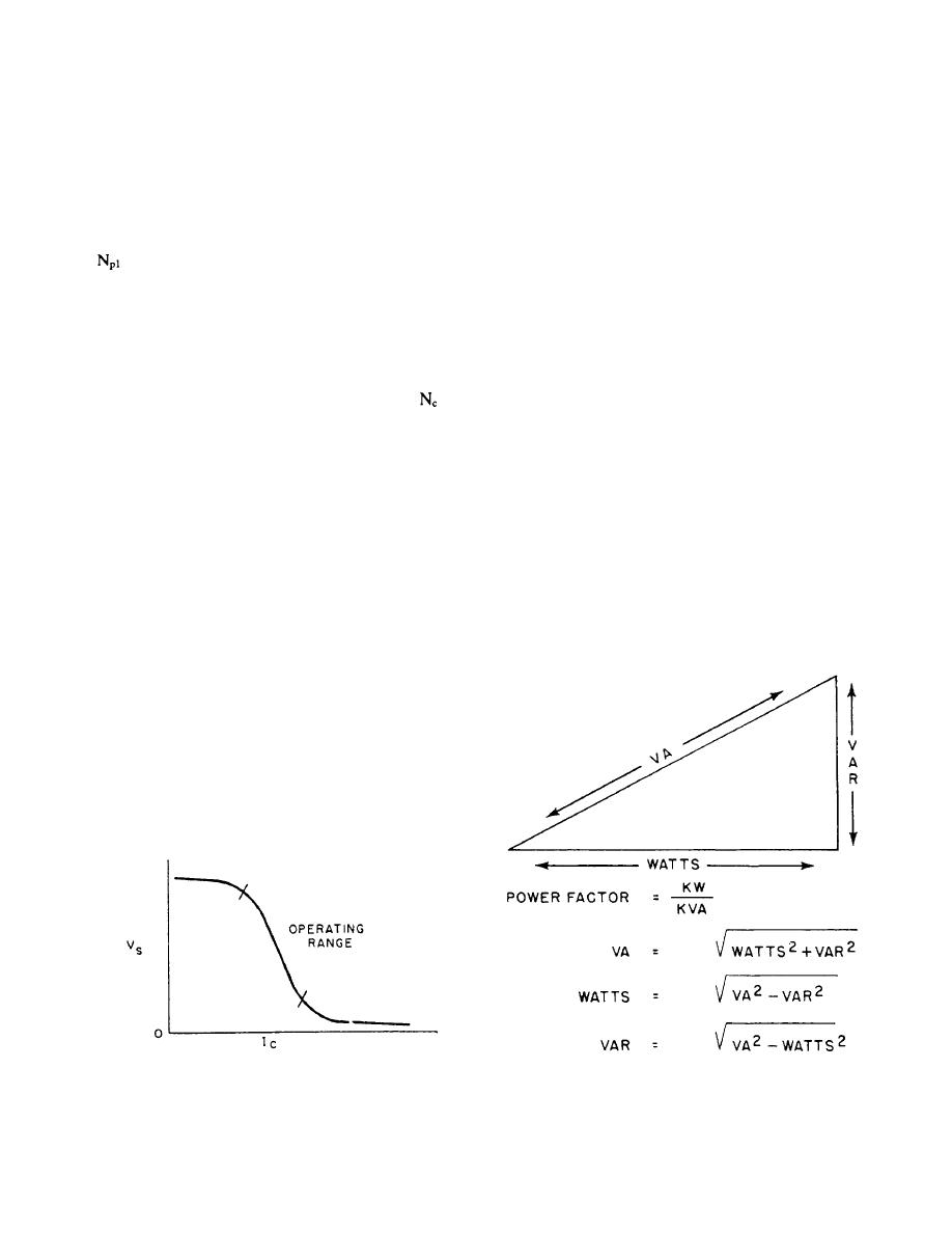
Figure 1-34.-Watt, VA, and VAR relationship. |
|
||
| ||||||||||
|
|
 30-kW load at unity power factor will result in a current
Saturation may be defined as the condition in the
magnetic material where an increase of magnetomotive
of only 38.5 amperes per line. The difference in the
force causes no increase in flux. The coupling of the
output current with identical kilowatt loads is the result
primary and secondary voltage is accomplished only
of the flow of reactive current in the load circuit. This is
known as the reactive volt ampere component of the
when there is a flux change; consequently, when the core
material is forced into the condition where no flux
load and is abbreviated VAR.
change can take place, the coupling of the primary and
This VAR component of the load is caused by the
secondary voltages becomes nonlinear, and the effect of
current of the generator being out of phase with the
de- coupling the secondary winding is produced. Fig-
voltage. The mathematical relationship of power factor,
ure 1-31 indicates the path of dc flux when the start of
watts, VA, and VAR is shown in figure 1-34.
is positive. Naturally, when the applied voltage
It is possible for the current to either lead or lag
polarity reverses itself, the fluxes, 01 and 02, also
behind the voltage, and, if it is lagging (for inductive
reverse themselves; but the dc flux through the control
reactive loads), the power factor would be a lagging
winding then forces 01 into saturation before 02 is
power factor.
forced into saturation. Since the load on the saturable
potential transformer secondary is magnetically coupled
The phase angle of the current in relation to the
to the primary of the saturable potential transformer, the
voltage of the generator output in combination with the
variable control current through the winding
will
magnitude of the output current is used by the
produce a variable secondary output voltage. The
power-sensing network to produce an output signal.
control current versus the output voltage characteristic
That signal will vary in magnitude in relation to the
of the saturable potential transformer is shown in fig-
useful output (kW) of the generator and will produce no
ure 1-33. The saturable potential transformer is designed
output when the generator load is entirely VAR. Any
to operate in the linear position of the characteristic
combination of VAR and kW will produce an output
curve, as shown in figure 1-33.
signal that is directly proportional to the kW load only.
The amount of power required by the motor to drive
POWER-SENSING NETWORK
the generator is also directly proportional to the kW
output of the generator. This makes it possible to use the
The power-sensing network functions to balance the
output signal of the power-sensing network with
load between generators operating in parallel. In single
changing load.
generator operation, the power-sensing network is not
used.
This network is designed to sense real power or the
kilowatt (kW) output of the generator only, as opposed
to kilovolt amperes (KVA) output.
This generating system has an output rating of 30
kW at 0.8 power factor, 37.5 KVA. The current in each
line with this load will be 48.5 amperes at 450 volts. A
Figure 1-33.-Characteristic curve of a saturable potential
Figure 1-34.-Watt, VA, and VAR relationship.
transformer.
1-28
|
|
Privacy Statement - Press Release - Copyright Information. - Contact Us |
