 |
|||
|
Page Title:
Figure 1-32.-Saturable potential transform. |
|
||
| ||||||||||
|
|
 The use of the SCPT is relatively new to
motor-generator application. Since the basic operation
of each core in the SCPT is identical, only one core will
be explained.
The basic operation of the SCPT is explained with
the aid of figure 1-31. It consists of two voltage primary
windings
and
two current primary windings
and
two secondary windings
and
and
a dc control winding
In figure 1-31, these windings are arranged on a
three-legged E-type lamination. For simplicity, consider
and
the leg of the transformer with windings
The
winding and the secondary winding (Vs1)
function like a normal power transformer, and the
current primary winding
and secondary winding
function like a normal current transformer. When either
or ) induce a voltage into
of the primary windings
the secondary winding
(the secondary winding is
connected to a load), a current will flow in the secondary
winding
The SCPT is constructed in such a
manner that the current flow in the secondary is the sum
of the current that would be caused to flow by the
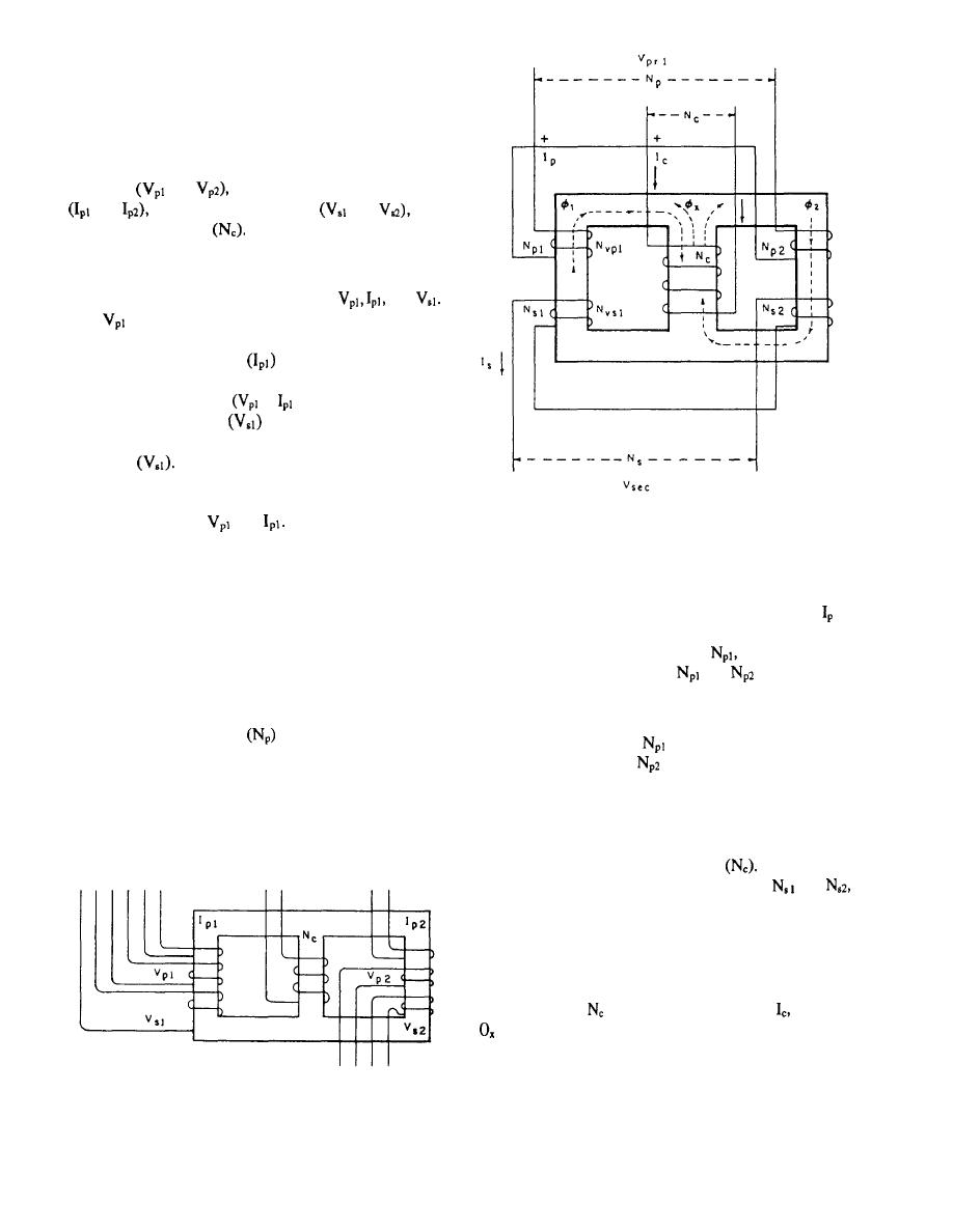
Figure 1-32.-Saturable potential transform.
and
As can be seen in fig-
separate windings
ure 1-31, there is a voltage and current primary winding
and a secondary winding on each of the cores of the
core, no voltage is induced into the control winding.
SCPT The function of each is as described in the
When voltage is applied to the primary windings,
previous paragraphs.
current flows in these windings, which are labeled in
figure 1-32. If the primary voltage is instantaneously
To understand the principle of operation of the dc
positive (+) at the start of winding
then the current
control winding, refer to figure 1-32. The action that
flowing through the turns of
and
should create
takes place between the primary winding (either current
the flux; 01 and 02, following the left-hand rule, which
primary or voltage primary), the secondary winding,
defines winding polarity.
and dc control winding is the same. Therefore, only a
voltage primary winding
is shown in figure 1-32.
The flux caused by
is in an upward direction,
The outer legs of the core are each wound with a primary
and the flux caused by
is in a downward direction.
and a secondary winding. The control winding is wound
These fluxes will close their loop through the center leg
on the center leg. The primary and secondary windings
of the laminated core because of the shorter path it
are connected so their flux oppose each other in the
presents; but because the fluxes are of equal magnitude,
center core. Thus, with the net flux of zero in the center
they cancel each other in the center leg and thus induce
no voltage in the control winding
Because the
fluxes, 01 and 02, link the secondary turns,
and
a voltage is induced in each of these with a sum of V
sec. The relationship that exists between the primary and
secondary windings when the core is not saturated is
identical to any voltage transformer with a core that is
not saturated. When a direct current flows through the
control winding
in the direction shown by a dc flux
is created, according to the left-hand rule, which is
in an upward direction opposing 01 and aiding 02. When
the magnitude of the dc flux becomes great enough,
Figure 1-31.-Saturable current-potential transformer.
it begins to force the core material into saturation.
1-27
|
|
Privacy Statement - Press Release - Copyright Information. - Contact Us |