 |
|||
|
|
|||
| ||||||||||
|
|
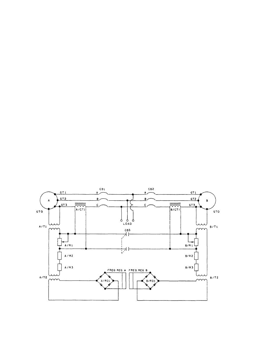 rheostat A/R1, thus disabling the power-sensing system.
A power-sensing network has been provided in one
If the leads from current transformer A/CT1 to resistor
phase of the generator output (fig. 1-35) for simplicity;
A/R1 are reversed, the phase relationship of the voltage
consider first the power-sensing circuit of generator A.
across resistor A/R1 would be 180 out of phase with
This circuit consists of current transformer A/CT1 and
the secondary of transformer A/T1. Therefore, with
real power-sensing rheostat A/R1. Note that power
increasing load, the regulator would try to raise the
transformer A/T1 is connected from neutral to line C,
output frequency of the generator. This is known as
and, therefore, the voltage across the primary of
frequency compounding.
transformer A/T1 will be in phase with the current in line
C at unity power factor. Transformer A/T2, which is the
frequency-sensing transformer, is in parallel with power
PARALLEL OPERATION
transformer A/T1, and, therefore, the voltage output of
the secondary of transformer A/T2 is in phase with the
voltage in the primary of transformer A/T1. Then, at
Refer to figure 1-35 and note that generator B has a
real power-sensing system exactly as generator A. Note
unity power factor, the voltage across the secondary
windings A/T2 will be in phase with the current in line
also that not only is current transformer A/CT1
C. Real power-sensing rheostat A/R1 is actually the load
connected across its load rheostat A/R1, but when circuit
resistor for current transformer A/CT1. Therefore, when
breaker CB3 is closed, it also is connected across real
power-sensing rheostat B/R1. Consider what would
a load is applied to the output of generator A, a voltage
happen if generator A were to supply the greater amount
will be impressed across rheostat A/R1, and this voltage
of real power to the load. There would be a difference
will be in phase with the voltage across the secondary
winding of transformer A/T1. The voltage from
in potential between current transformers A/CT1 and
B/CT1. Due to the difference in potential, a current will
transformer A/T2 and the voltage across resistor A/R1
flow in resistors A/R1 and B/R1 connected in parallel.
will add, and the sensed voltage will be an increased
The current will be in phase with the voltage out of
voltage to rectifier A/RD1. This would represent an
secondary of transformer A/T1 and 180 out of phase
increased output frequency; thus, the regulator would
with the secondary voltage of transformer B/T1. Hence,
decrease the speed of the motor and thus reduce the
output frequency of the generator. This is known as a
the regulator of generator A will decrease its output
frequency droop. To eliminate this droop in singular
output frequency. This will permit the generator to
operation, a shorting bar or relay contact is placed across
Figure 1-35.-Power sensing.
1-29
|
|
Privacy Statement - Press Release - Copyright Information. - Contact Us |
