 |
|||
|
Page Title:
Figure 8-17.--Location of automatic degaussing coils. |
|
||
| ||||||||||
|
|
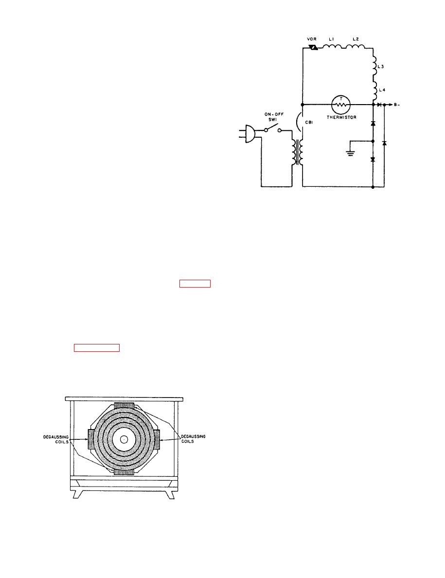 Automatic Degaussing
The metal aperture mask often becomes
magnetized when the receiver is moved through the
earth's magnetic field, Metal parts in and around the
picture tube also become magnetized when a
man-made magnetic field collapses or expands in
close proximity to the receiver. If these stray fields are
allowed to exist, the electron beam from each gun will
strike the incorrect phosphor dots on the face of the
screen, causing color impurities. Unless the parts have
become permanently magnetized due to a prolonged
exposure to a strong magnetic field, the magnetism
can be canceled by the process of degaussing. During
degaussing, a controlled magnetic field is developed
by passing alternating current through coils of wire.
The magnetic fields thus produced not only cancel the
existing stray magnetic fields but also serve to prevent
schematic diagram.
any future buildup.
In modem color receivers, the problem presented
by stray magnetism is somewhat alleviated by
When the on-off switch is initially closed, the
automatic degaussing coils. These coils are an integral
resistance of the thermistor is high and nearly all of
part of the color receiver and are usually activated each
the circuit current flows through the degaussing coils.
time the receiver is turned on. The coils, usually from
After the first few seconds, degaussing is complete
two to four in number, are evenly spaced around the
and it is necessary to remove the coils from the circuit.
magnetic shield of the receiver picture tube (fig. 8- 17).
Coil isolation is completed by using the combined
Of the many circuits designed to provide
properties of the VDR and the thermistor. After the
automatic degaussing, the voltage dependent resistor
first few seconds of operation, the resistance of the
thermistor begins to decrease due to the current
(VDR) thermistor circuit arrangement is the most
flowing through the circuit. Simultaneously, the VDR
popular method of obtaining trouble-free operation,
The schematic diagram of such an arrangement is
begins to increase in resistance because less voltage is
shown in figure 8-18. The circuit consists of a
now applied. The combined action of the two special
thermistor, a voltage dependent resistor, and the four
resistors results in the coils eventually being
degaussing coils.
electrically removed from the circuit.
TELEVISION ENTERTAINMENT
SYSTEM
The television entertainment system (circuit
15TV) receives VHF broadcast television signals and
amplifies and broadcasts the signals to various
locations throughout the ship. The system consists of
a signal amplifier, a signal splitter, line taps, TV
signal/duplex power receptacle outlet boxes,
impedance matching transformers, and standard
commercial television receivers. The system is
basically passive except for the amplifier, which
requires 115-volt, 60-Hz, single-phase power.
|
|
Privacy Statement - Press Release - Copyright Information. - Contact Us |
