 |
|||
|
Page Title:
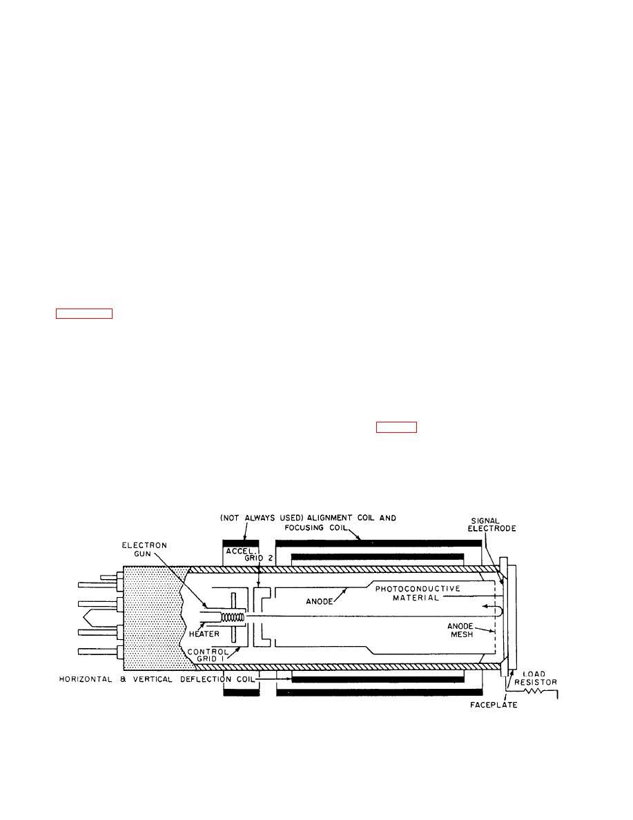
Figure 8-10.--Structure of the vidicon tube. |
|
||
| ||||||||||
|
|
 The image orthicon may be used for indoor or
dark. When an image is formed on the target by the
outdoor TV pickups. With this tube, scenes may be
camera lens, each element becomes conductive in
proportion to the amount of light falling upon it.
televised under light levels as low as 3 foot-candles
illumination (ordinary room lighting). However, light
Electrons flowing from the lowered resistance of the
levels of approximately 30 foot-candles provide
illuminated elements leave an electrical pattern on the
scanning side of the photoconductive layer. The
broadcast quality results. This is important in some
Navy applications.
electrical pattern formed corresponds to the light areas
of the optical image. The time required for the pattern
Vidicon
to form is less than the time of one television frame.
As the electron beam scans the electrical pattern
The vidicon is a small television camera pickup
of the optical scene, electrons flow to the elements
tube. Its relative simplicity and small size permit its
having the most positive charges. The small current
use in television cameras of very compact design. All
generated in each element flows through the
vidicons are similar, differing primarily in specific
transparent conducting film, the signal electrode, and
size, sensitivity, and resolution.
the load resistor to develop the video output signal.
When the beam scans a dark area, each element in the
The target area of the vidicon tube is made up of
two layers. The outer layer is a transparent conducting
dark area becomes negatively charged. When this
film on the inner surface of the glass faceplate. The
occurs, most of the beam is turned back. When the
entire surface is dark, a very small current flows to the
inner layer is a photoconductive material on the
load resistor and is called the dark current.
scanning side of the signal electrode. This is illustrated
in figure 8-10. The low-velocity beam is focused at the
Vidicons should always be handled and shipped
target surface by the combined effects of the
face up. Turning the tube face down could cause loose
electromagnetic focus coil and the electrostatic focus
particles within the tube to spot the surface.
field. A fine mesh screen is located near the
photoconductive layer. This screen forms a uniform
TYPES OF LENSES
decelerating field with the photoconductive layer,
which the beam passes through. This field causes the
The desired type of image or the size of camera
beam to land perpendicular upon the surface of the
coverage requires different types of lenses. The size
target. The electron beam is made to scan the
of the lens (fig. 8-9) varies from small and short to
photoconductive layer by the vertical and horizontal
large and long. The purpose of the various lenses
deflection coils.
varies from the wide-angle lens for large area coverage
to the telephoto lens for narrow coverage at long
Each small element of the photoconductive
distances.
material acts as an insulator when the element is in the
8-13
|
|
Privacy Statement - Press Release - Copyright Information. - Contact Us |
