 |
|||
|
Page Title:
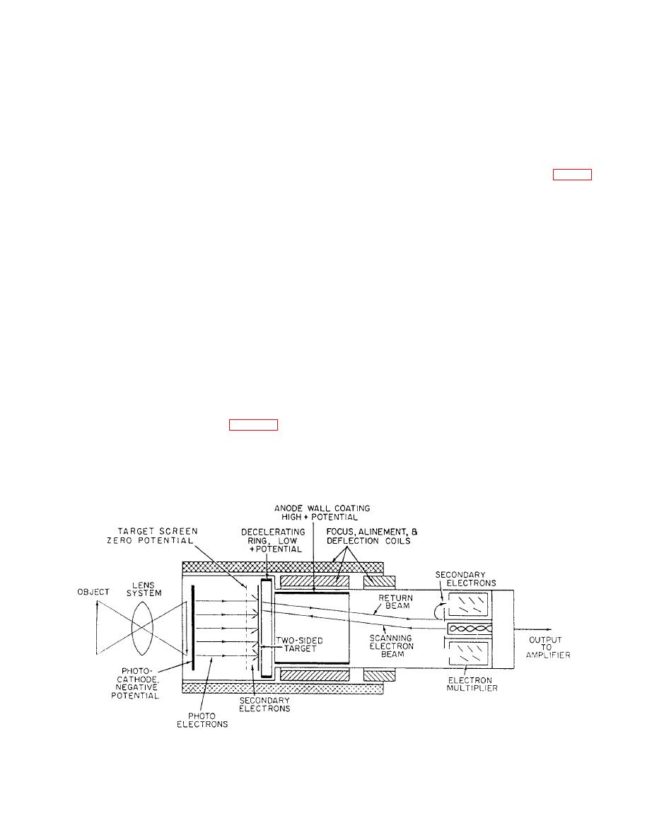
Figure 8-9.--Structure of image orthicon. |
|
||
| ||||||||||
|
|
 frequencies and separate and demodulate the video
(photocathode) by the camera lens. Electrons are
and audio frequencies. They must be separated to use
released from the photocathode in proportion to the
the sync pulses to reproduce the picture on the screen
intensity of the light striking it.
and sound at the speaker. How well each job is done
The released photoelectrons are directed on
depends largely on the design and quality of the TV
parallel courses from the photocathode through the
receiver.
target screen, to the two-sided target. This is done by
When the signal in CCTV is sent from the camera
an electrostatic field between the target screen and the
to the viewing unit by cables, there are no antenna
photocathode. Electrons are released from the target
problems. However, where the control unit contains a
by the impacting photoelectrons. This leaves a pattern
small oscillator, which furnishes an amplitude
of positive charges on the front of the target (fig. 8-9).
modulated video signal, the viewing unit must have a
The released electrons are collected by the target
tunable receiver.
screen, which has a slightly positive charge relative to
the target.
CAMERA TUBES
The back of the target is scanned by a beam from
an electron gun in the base of the tube. The beam is
The objective of television camera tubes is to
slowed to a near zero velocity at the target by the
convert an image into a continuous electrical signal.
decelerating ring. This is to avoid producing unwanted
The image can be a live scene, a series of
motion-picture frames, or a still picture. The signal
secondary electrons on the back side of the target. If
from the tube consists of a succession of voltages
the point on the target the beam approaches has a
proportional to the light intensity of each individual
positive charge, it extracts enough electrons from the
element encountered in the scanning process.
beam to become neutral. The remaining electrons in
the beam travel back toward the aperture. The aperture
The two types of camera tubes we will discuss in
is a good emitter of secondary electrons, thus
this chapter are the image orthicon and the vidicon.
providing amplification of the return beam. The
secondary electrons are directed into the electron
Image Orthicon
multipliers, where the signal is amplified, to a value
great enough to be fed into a video amplifier. The
The image orthicon tube (fig. 8-9) is an
focus, alignment, and deflection coils, along with
ultrasensitive camera tube used in modem television
special grids, keep the various streams in all parts of
systems. This tube picks up a light image from the
object that is focused on the light-sensitive face
the tube under proper control.
8-12
|
|
Privacy Statement - Press Release - Copyright Information. - Contact Us |
