 |
|||
|
Page Title:
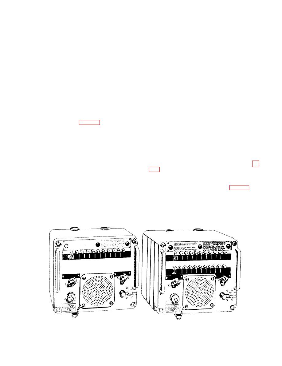
Figure 7-31.--Intercommunicating units, types LS-518/SIC and LS519/SIC. |
|
||
| ||||||||||
|
|
 position and depress release push button S 1 on the unit
connecting terminal 2X to terminal XX. When station
under test. This test checks the continuity between
selector push button S2 on the unit under test is
terminals 2 and 2C through switch S2U and busy relay
depressed to select station 2, it checks the busy circuit
K2 to the line winding terminals 14 and 15 of
through lower switch assembly S2L, busy relay K2,
latchbar switch S23, and associated wiring. It also
transformer T2.
checks the operation of upper switch assembly S2U and
Similarly, on the unit under test, depress the
associated wiring.
remaining station selector push buttons, S3 through S11,
Test the remaining push buttons by operating first
using the corresponding test switches, S203 through
S211, on the test fixture for each test. This test checks
the test switches, S204 through S211, to the TEST
the continuity of the various audio circuits. If the unit
position on the test fixture, and then depressing the
under test is provided with facilities for originating calls
corresponding station selector push buttons, S4 through
to 20 stations, repeat the foregoing tests, using the
S11, on the unit under test. If the unit under test is a
second row of station selector pushbuttons, S12 through
20-station type, repeat the foregoing tests, using the
S21.
second row of station selector pushbuttons, S12 through
S21.
Signal Circuit Test
The manufacturer's technical manual furnished
with the equipment installed in your ship contains more
On the test fixture (fig. 7-30), operate talk test
detailed information concerning the operation, repair,
switch S213 to the OFF position and the 11 test switches,
and maintenance of intercommunicating units.
S201 through S211, to the STANDBY position. On the
unit under test, depress release push button S1 for the
INTERCOMMUNICATING UNITS
subsequent signal circuit tests.
LS-518/SIC AND LS-519/SIC
On the test fixture, operate test switch S202 to the
TEST position, and on the unit under test, depress
The N-518/SIC and LS-519/SIC intercoms (fig.
station selector push button S2. Busy lamp I1 should
light. On the unit under test, depress release pushbutton
Both are fully transistorized intercoms that operate in
S1, and again depress station selector switch S2. Busy
much the same way as the older 433A and 434A types
lamp I1 should go out and again light. Repeat this test
(refer to the overall functional diagram, fig. 7-32). The
several times in rapid succession. On the test fixture,
darkened solid line in this figure shows that the audio
restore test switch S201 to the STANDBY position, and
from the calling loudspeaker is amplified and
on the unit under test, depress release push button S1.
transmitted via the station selector switches to the called
When test switch S202 on the test fixture is operated
station. The darkened broken line shows that the audio
to the TEST position, it makes station 2 busy by
from the calling station goes into the speaker of the local
Figure 7-31.--Intercommunicating units, types LS-518/SIC and LS519/SIC.
|
|
Privacy Statement - Press Release - Copyright Information. - Contact Us |
