 |
|||
|
Page Title:
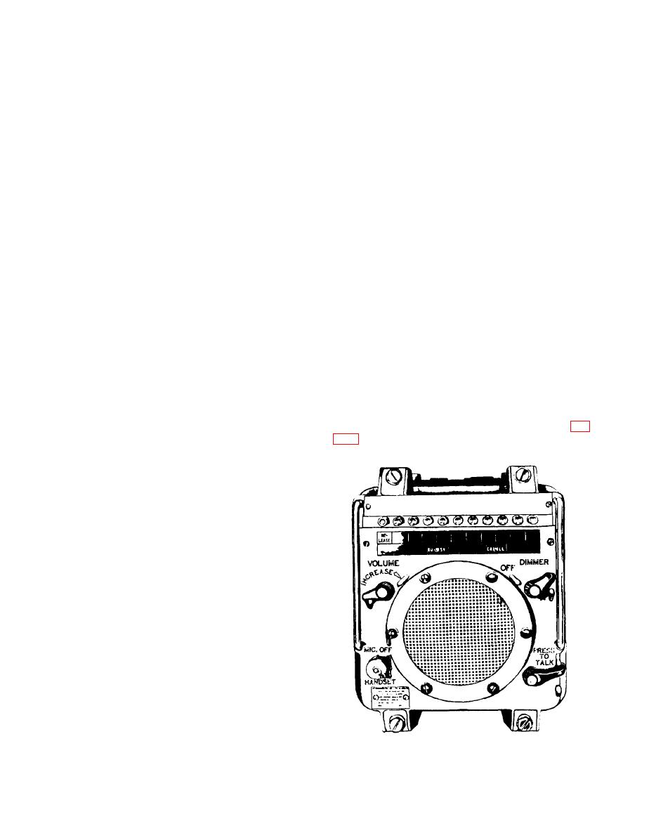
Figure 7-28.--Intercommunicating unit (LS-433A/SIC). |
|
||
| ||||||||||
|
|
 prevents multiple inputs to the amplifier, which could
B amplifier, place all loudspeaker group control
result in unintelligible transmissions to the remote
switches to channel A. When operating under this
loudspeakers.
condition, with all loudspeaker groups connected to one
amplifier, be careful not to overload the amplifier. Use
The microphone control stations located at the
the OUTPUT TEST switch and meter to test the output
remote stations consist of a flexible microphone and an
of the channel in use. Proper output is indicated when
associated microphone jackbox. These remote stations
the meter fluctuates with peaks occuring about midscale
are connected to the amplifier as separate inputs.
(0 dB).
Loudspeakers
INTERCOMMUNICATION SYSTEMS
Loudspeakers are located in the sonar control area
and at each remote location. Loudspeakers located
Intercommunication (intercom) systems provide
adjacent to control stations are wired so that they are
for two- way transmissions of orders and information
disconnected from the amplifier when the adjacent
between stations. Each intercom unit contains its own
control station is operated.
amplifier.
MAINTENANCE
INTERCOMMUNICATING UNITS
Maintenance of the system consists of routine
LS-433A/SIC AND LS-434A/SIC
preventive maintenance and corrective maintenance.
Maintenance for the two-way system is essentially the
Regardless of their construction, intercommunicat-
same as for the one-way system. Routine preventive
ing units on naval vessels are connected together
maintenance consists of inspecting, cleaning, and
electrically in a system. The electrical characteristics
t e s t i n g . Corrective maintenance consists of
that must be identical to permit interconnection in a
troubleshooting and replacing parts.
system are (1) audio-amplifier input and output
requirements, (2) amplifier output impedance to the
As with the one-way system, operation of this equip-
loudspeaker line transformer, (3) supply voltages and
ment involves the use of high voltages with no interlocks
currents, (4) call and busy signal voltages, and (5)
provided. Therefore, all safety regulations and
interconnection circuits.
precautions must be observed at all times when you are
performing corrective maintenance on this equipment.
One type of intercom unit, the LS-433A/SIC (fig.
Malfunctions can usually be localized by using the
comparison method. A problem common to all
microphone control stations usually indicates a failure
within the circuits of the control rack. A problem
peculiar to only one station indicates the fault could be
located in the control rack the microphone control
station, or the cables connecting the control station to
the control rack.
If the entire system is inoperative, check the
POWER AVAILABLE indicator lamp on the control
rack. If the lamp is not lit, check the switch that provides
power to the control rack. If the lamp is lit, check the
position of the switches on the control panel. If all the
control panel switches are in their proper positions,
check for blown fuses. If there is no indication of a
blown fuse(s), refer to the applicable technical manual
and schematic diagram for the system.
The system's dual channel design, with switching
controls, permits continued operation of the system
when one channel fails. If there is a failure of the channel
A amplifier, place all loudspeaker group control
switches to channel B. If there is a failure of the channel
|
|
Privacy Statement - Press Release - Copyright Information. - Contact Us |