 |
|||
|
Page Title:
Figure 7-13.--Block diagram of the general alarm module. |
|
||
| ||||||||||
|
|
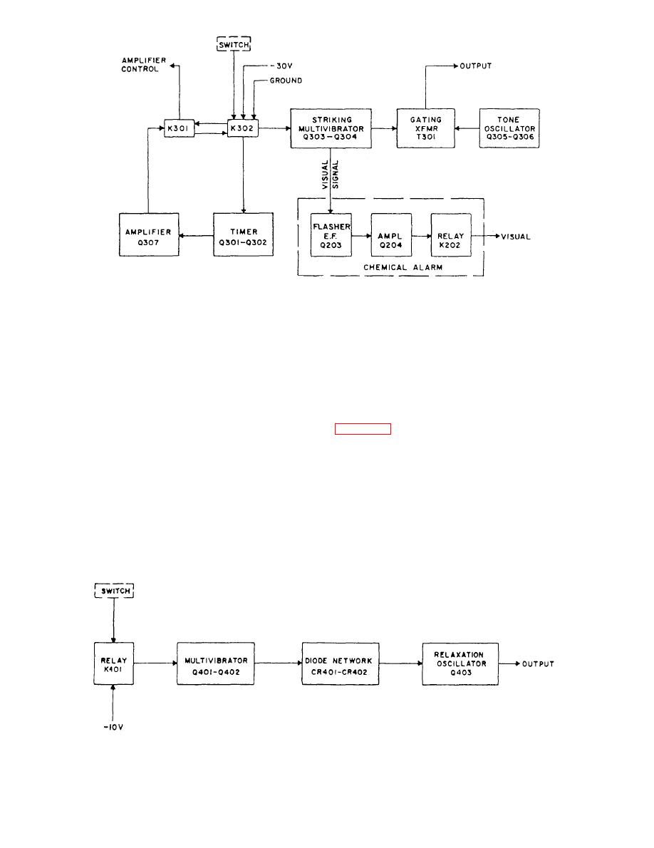 the general alarm contact maker will energize relay
amount of time the alarm will continue sounding after
K302, which will ground all stages fed with -10 volts
the alarm contact maker is released. Normal adjustment
dc. K302 also supplies -30 volts dc to transistor Q307
is for a 15-second hold.
through relay K301, thus energizing K301, which holds
UNASSIGNED A ALARM.-- The unassigned A
K302 energized and supplies control voltage to the
alarm contains transistorized oscillator and timer
amplifier.
circuits that generate 500-Hz and 1500-Hz sine waves
The striking multivibrator also supplies a signal to
alternating at a rate of 1 1/2 Hz, producing a jump tone.
transistors Q203 and Q204 in the chemical alarm circuit,
causing K202 in the chemical alarm circuit to operate
module. Operation of the unassigned A alarm contact
every time the gong strikes at the rate of 100 times per
maker supplies -10 volts dc through relay K401 to all
minute, causing the visual signal to flash.
stages of the circuit.
Resistor R311 (not shown) is a trimpot used in the
Resistor R406 (not shown) is a trimpot used in the
circuit to adjust the rate at which the alarm strikes.
circuit to adjust the high-frequency tone. Resistor R408
Clockwise rotation speeds up striking, while
(not shown) is a trimpot used in the circuit to adjust the
counterclockwise rotation reduces it. Normal
low-frequency tone. If adjustment is required, you
adjustment is for 100 strokes per minute. Resistor R302
should always make the low-frequency adjustment first.
(not shown) is a trimpot used in the circuit to adjust the
The normal setting is 500 cycles per second for the low
7-13
|
|
Privacy Statement - Press Release - Copyright Information. - Contact Us |
