 |
|||
|
Page Title:
Figure 7-11.--Block diagram of the collision alarm module. |
|
||
| ||||||||||
|
|
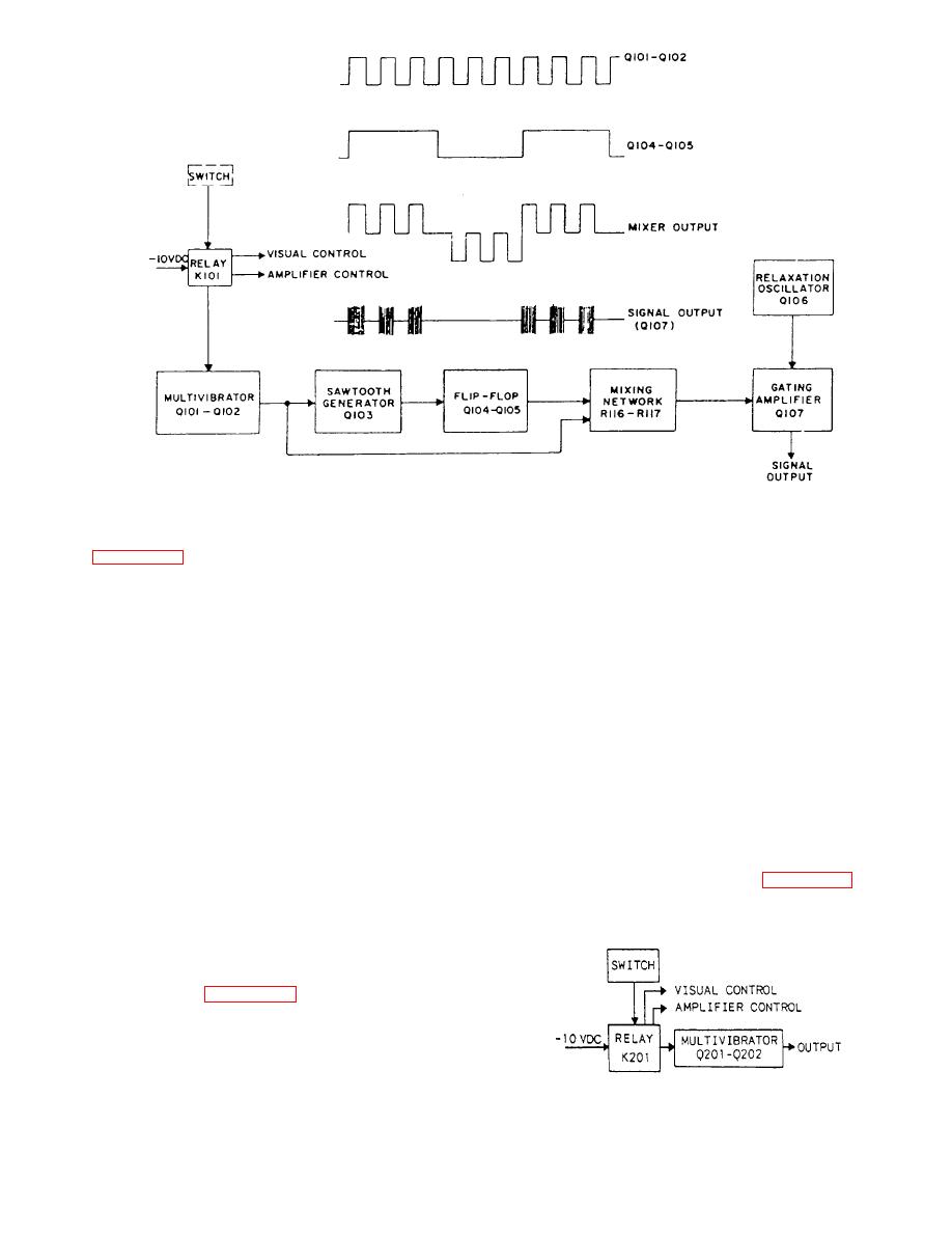 Resistor R203 (not shown) is used in the circuit to
adjust the frequency to precisely 1000 Hz. Clockwise
module. Operation of the collision alarm contact maker
rotation of the pot will increase the frequency, while
will supply -10 volts dc to all stages in the circuit through
counterclockwise rotation will decrease the frequency.
relay K101. K101 will also apply control voltage to
operate the visual signal circuit and the amplifier
There are also two other transistors in the chemical
channel.
alarm circuit. These transistors are associated with the
general alarm and will be discussed later.
Resistor R107 (not shown) is a trimpot used in the
circuit to adjust the number of pulses in a group.
GENERAL ALARM.-- The general alarm
consists of a 400-cycle per second rectangular wave
Clockwise rotation of the pot will decrease the number
oscillator coupled through a gated transformer. A
of pulses, while counterclockwise rotation will increase
striking multi vibrator supplies current to a diode across
the number of pulses. Resistor R127 (not shown) is a
the gating winding of this transformer that produces the
trimpot used in the circuit to adjust the frequency to
decaying characteristics of a gong. A timing
exactly 1000 Hz. Clockwise rotation of the pot will
multivibrator and relay holds the operating relay in the
increase the frequency, while counterclockwise rotation
operating position for a period of 10 to 15 seconds after
will decrease the frequency.
the alarm contact maker is released. Figure 7-13 is a
block diagram of a general alarm module. Operation of
transistorized oscillator circuit that generates a
continuous 1000-Hz signal as long as power is applied
to the circuit. This circuit consists of a square wave
multi vibrator. Figure 7-12 is a block diagram of a
chemical alarm module. Operation of the chemical
alarm contact maker will supply -10 volts dc to the
circuit through relay K201. Relay K201 will also apply
control voltage to operate the visual signal circuit and
the amplifier channel.
7-12
|
|
Privacy Statement - Press Release - Copyright Information. - Contact Us |
