 |
|||
|
Page Title:
Figure 6-42.--Link panel test set. |
|
||
| ||||||||||
|
|
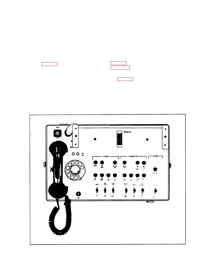 operating the appropriate lever switches and the
Test Equipment
selector switch, various system conditions are
Preventive maintenance must be performed on the
simulated. The module response is indicated by the
MDM system to keep it in good operating condition
various test lamps located on the panel. The switches
and lamps are connected so that the three modules
and to prevent interruptions in service. When
tested use many common test set components. The test
corrective maintenance is required, special test
set requires an external source of ring voltage and dc
equipment is needed to complete the work. In the
power. These normally can be obtained from terminals
following paragraphs the major special test equipment
located at the switchboard.
for the MDM system will be discussed.
The description of controls and indicators listed in
COMMON PANEL TEST SET.-- The common
panel test set (fig. 6-41) is used to test the common
control, link allotter, and level detector circuit
modules of the MDM 50- and 100-line units out of the
LINK PANEL TEST SET.-- The link panel test
system. The purpose and function of the 50/100-line
set (fig. 6-42) is similar to the common panel test set.
system and the 200/700-line system are the same.
It is also used on the 50/100-line system. The one used
There are some physical characteristics that are
for the 200/700-line system functions in the same way
different. The module to be tested is plugged into the
but has some physical differences. It is used to bench
test the link circuit modules. To test the module, the
jack receptacle located on the face of the test set. By
|
|
Privacy Statement - Press Release - Copyright Information. - Contact Us |
