 |
|||
|
Page Title:
Figure 6-23.--Ringing generator, cover removed. |
|
||
| ||||||||||
|
|
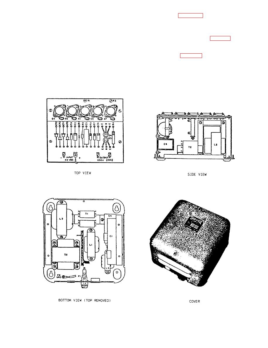 RINGING GENERATORS.-- The switchboard
panel in cabinet 2. Figure 6-23 is an illustration of a
has two ringing generators, which are mounted on a
ringing generator with the cover removed.
baseplate at the bottom of cabinet 2. The generators
are transistorized units, which supply ringing current
GROUND FAULT DETECTION PANEL.--
at 20 Hz, 75 to 110 volts to station telephones. The
The ground fault detection panel (fig. 6-24) detects
generators are wired so that one is active (on line) and
shorts and/or leakage paths from the ship's wiring to
the other is in a standby condition. Should the on-line
the ship's hull. This panel is located in the lower right
generator fail, manual transfer to the standby
comer of cabinet 2. Table 6-5 describes the controls
generator is required. The manual transfer switch
and indicators located on the ground fault detection
(RG1 20HZ/RG2) is located on the switch and fuse
panel.
6-26
|
|
Privacy Statement - Press Release - Copyright Information. - Contact Us |
