 |
|||
|
|
|||
| ||||||||||
|
|
 51.6-volt dc and +5 and +12 volt dc logic voltages. The
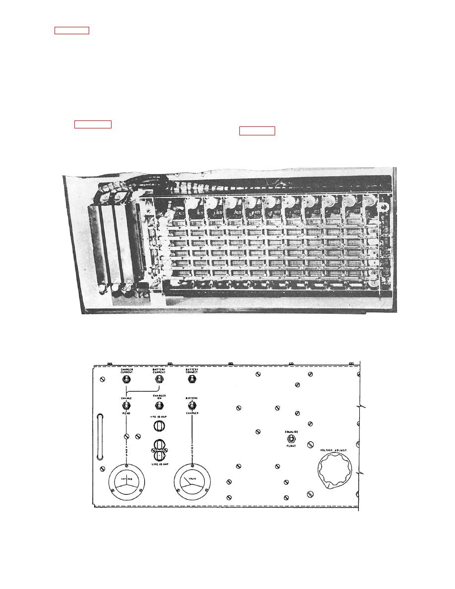
switch (fig. 6-21) consists of a welded rectangular
51.6-volt dc is used to trickle charge and equalize
frame that houses 10 vertical (hold) units, 6
charge a 24-cell battery bank. The battery bank is
horizontal select bars, 12 select magnets, and 12
used as an emergency input for the power supply
select off-normal spring pile-ups. Each switch can
when the input from the main IC switchboard fails.
connect 10 sets of three conductors each to any of 30
In the event there is a failure, the power supply
sets of three conductors each. This means one switch
automatically shifts to the battery input. The +5 and
can handle up to 10 connections at any given time.
+12 dc logic voltages are used as inputs to the circuit
All paths are electrically isolated from each other.
card assemblies. Input line filters are also used in the
power supply to prevent line voltage surges from
affecting the output voltage of the power supply.
supply (fig. 6-22) receives a 115-volt, 60-Hz, single-
phase input from the main IC switchboard. The
and indicator-type fuses located on the power supply,
power supply takes this input and internally develops
Figure 6-21.--Crossbar switch.
|
|
Privacy Statement - Press Release - Copyright Information. - Contact Us |
