 |
|||
|
Page Title:
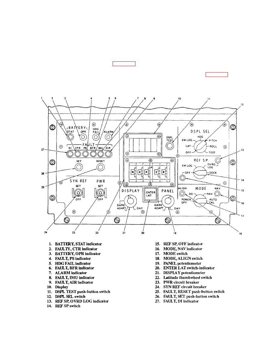
Figure 4-44.--Controts and indicators. |
|
||
| ||||||||||
|
|
 The cabinet contains a wiring harness, alarm relays,
major assemblies. The five major assemblies are
power relays, electromagnetic interference (EMI)
contained within the cabinet. These assemblies are the
filters, an elapsed time meter, capacitor assemblies, a
control indicator, control power supply, battery set,
blower for IMU cooling, and the IMU rack. A connector
synchro signal amplifier, and inertial measuring unit
panel located on the rear of the cabinet provides the
(IMU).
electrical cable interconnections for cabling to external
equipment, including primary power.
Electrical Equipment Cabinet
Control Indicator
The electrical equipment cabinet (fig. 4-43)
provides the mechanical and electrical interface for the
The control indicator (fig. 4-44) is a hinged
five major assemblies. The cabinet also provides forced
assembly located in the top of the electrical equipment
air cooling for the IMU.
4-46
|
|
Privacy Statement - Press Release - Copyright Information. - Contact Us |
