 |
|||
|
Page Title:
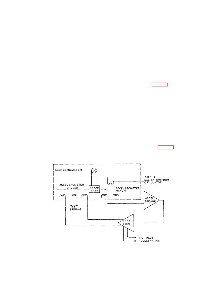
Figure 4-42.--Accelerometer control loop. |
|
||
| ||||||||||
|
|
 An additional circuit called a fault protector has
Securing the Mk 19 Mod 3B
been added. This unit receives inputs from the current
Gyrocompass
and voltage sensing circuits and sends an output or fault
The procedures for securing the Mk 19 Mod 3B
signal to the inverter drivers to expedite correction for
gyrocompass are the same as for the Mk 19 Mod 3A
overcurrent or other output faults.
gyrocompass.
Another major change in the Mk 19 Mod 3C
compass is the replacement of the electrolytic level in
the gravity reference system (Mk 19 Mod 3A and Mod
MK 19 MOD 3C GYROCOMPASS
3B) with an accelerometer. The accelerometer is a more
SYSTEM
accurate detector than the electrolytic level.
The Mk 19 Mod 3C gyrocompass system uses a
The meridian gravity reference system of the 3A
modified version of the static standby power supply
gyrocompass was discussed earlier in this chapter. In
used in the Mk 19 Mod 3B. This modified version,
modification 3C, the system consists of two closed-loop
known as the static power supply, is used as the primary
systems: the accelerometer control loop and the
power supply as well as the standby supply for the
speed-tilt computer loop (fig. 4-41). The system detects
compass. The static power supply receives 115-volt,
any horizontal deviation of the gyro spin axis and
400-Hz power from the ship's supply and, in turn,
supplies a signal proportional to the amount of tilt to the
supplies the compass with a highly reliable 3-phase,
115-volt, 400-Hz power. If the ship's supply fails or falls
The accelerometer senses any accelerations in the
below 112 volts, the static power supply automatically
north-south plane as well as tilting of the gyro spin axis.
receives its power from the storage batteries.
The accelerometer control loop cannot distinguish
between tilting and accelerations, and its output signal
Another feature incorporated in the static power
to the speed-tilt computer contains acceleration and tilt
supply is a servicing switch on the inside of the panel
signals. The output signals would be basically the same
door. When the servicing switch is in the OFF position,
for northerly accelerations as for a tilt of the spin axis
the incoming ship's supply and the battery supply are
broken. When the servicing switch is in the READY
The speed-tilt computer accepts the output of the
position, the ship's supply and the battery supply circuits
accelerometer control loop (fig. 4-42) and determines
are lined up for normal operation.
|
|
Privacy Statement - Press Release - Copyright Information. - Contact Us |
